Fujitsu and the Fujitsu Research Institute have announced that they have developed technologies that improve the sensitivity of signal receiving IC chips for large-capacity wireless communication devices using the millimeter wave band (240 GHz band). This technology is related to the amplifiers that make up the receiver, which prevents oscillations caused by leakage signals and increases the amplification factor.
With the increasing demand for data communication for devices such as smart phones, the millimeter wave band with a bandwidth of more than 100 times the frequency of existing mobile phones is expected. However, in the millimeter wave band (30G to 300 GHz), when the extremely high frequency of 240 GHz is reached, the wave propagating in space is greatly attenuated. Therefore, it is necessary to use a high-sensitivity receiver (composed of an antenna, an amplifier, and a detector) that can receive a weak signal, and in order to effectively improve the receiving sensitivity, it is necessary to increase the amplification factor of the amplifier.
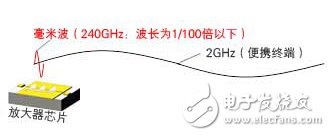
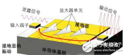
In the 240 GHz band, the wavelength of the signal is extremely short, less than 1 mm, which is smaller than the chip size of the amplifier (Figure 1). At this time, the following new problems will occur: part of the output signal of the amplifier will leak to the ground plane (electrical reference plane) formed on the surface of the amplifier chip. These leakage signals will be returned to the input terminal of the amplifier and input into the amplifier again. Figure 2), and the signal input again is amplified by the amplifier, and becomes a larger leakage signal and returns to the input terminal again. This is an oscillation phenomenon, which may cause the receiver to not receive the signal normally. To achieve higher magnification in millimeter waves, it is necessary to employ a technique that suppresses such oscillation without loss of magnification. Fujitsu and Fujitsu Research have developed the following two technologies based on the Fujitsu Institute's Indium Phosphide High Electron Mobility Transistor (InPHEMT) technology.


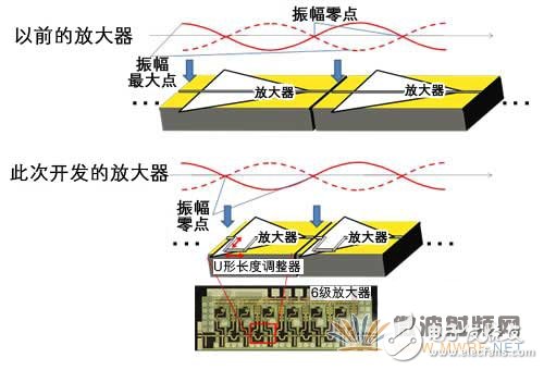
The leakage signal of the amplifier has an amplitude maximum point at which the amplitude increases at a specific position and an amplitude zero point at which the amplitude does not vibrate at all. When the position of the amplifier's input terminal coincides with the maximum amplitude of the leakage signal, a larger leakage signal is input to the amplifier, causing oscillation (Figure 3). When the input terminal is at the zero point of the amplitude, the leakage signal will not vibrate at all, and the amplifier will not amplify the leakage signal. Therefore, the position of the input and output terminals of the amplifier can be made to match the amplitude zero of the leakage signal (see Figure 3 below). By connecting the amplifiers thus designed in multiple stages, the amplification factor can be increased without causing oscillation.
In order to efficiently transmit the output signal of the amplifier to the next stage amplifier, the line connecting the amplifier must be impedance matched, for which a certain line length must be guaranteed. However, when the input/output terminals of the amplifier are aligned with the amplitude zero position, the size of the amplifier is limited, and the line is also limited to a specific length, so impedance matching is very difficult. By adopting a U-shaped line and adjusting the longitudinal and lateral lengths of the U-shape, the R&D personnel obtained the result of impedance matching even if the amplifier size is limited.

Figure 3 The previous figure shows the previous amplifier. The figure below shows the amplifier developed this time.

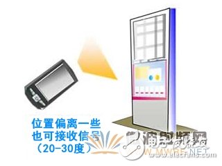
Figure 4 schematic diagram of terminal use
According to reports, by using these technologies, the sensitivity of the receiving IC can be increased by about 10 times. If the IC is equipped with a smart phone such as a small antenna, you can use an antenna with more directivity than the original, so you don't have to align the angle of the terminal with the transmitter (Figure 4). User's convenience. In the future, Fujitsu will continue to develop an antenna-integrated small package that can package such a receiving IC. It is planned to carry out transmission experiments in the near future, and it will be put into practical use around 2020.
Description of self closing braided sleeving
PET White Self Wrapping Split Braided Sleeving for cable management (PET woven mesh tube) is braided by environment friendly polyester monofil. PET is with good flexibility, fire resistance, abrasive resistance and thermal insulation performance. The sleeving are smooth surface, bright color, various patterns.
self-closing wrap offers innovative solutions for the protection of breakout areas and provides easy removal when is necessary an inspection or maintenance of cables. The special open structure allows to be installed after other components, for example copper terminals and connectors.
Features of Self Closing Braided Wrap For Cable Management
• Easy, cost and labor effective installation
• More flexible than split convoluted or spiral wrap
• 50% edge overlap
• Cut and abrasion resistant
• Halogen free
• Retains shape and rigidity throughout -50°C to 150°C temperature range
• melt temp. 250°C
Split Braided Sleeving,Split Loom Cable Wrap ,Self Cable Sleeving,Pp Self Wrap Sleeve
Shenzhen Huiyunhai Tech.Co.,Ltd , https://www.hyhbraidedsleeve.com