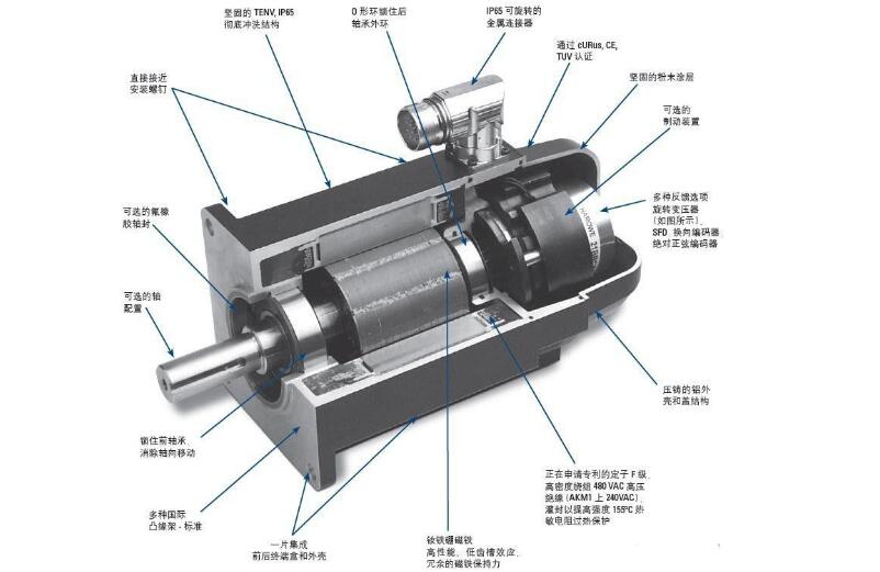
The servo is mainly positioned by pulse. When the servo motor receives one pulse, it will rotate the angle corresponding to one pulse to realize the displacement. Because the servo motor itself has the function of emitting pulses, the servo motor will emit every angle. Corresponding number of pulses, so that the pulse received by the servo motor forms an echo, or closed loop, so that the system knows how many pulses are sent to the servo motor, and at the same time, how many pulses are received, so that it can be very Precise control of the rotation of the motor for precise positioning up to 0.001 mm. The rotor inside the servo motor is a permanent magnet. The U/V/W three-phase electric motor controlled by the driver forms an electromagnetic field. The rotor rotates under the action of the magnetic field. At the same time, the encoder feedback signal from the motor is supplied to the driver. The driver according to the feedback value and target. The values ​​are compared to adjust the angle at which the rotor rotates. The accuracy of the servo motor is determined by the accuracy (number of lines) of the encoder.
DC servo motors are divided into brushed and brushless motors. The brush motor has low cost, simple structure, large starting torque, wide speed regulation range, easy control and maintenance, but convenient maintenance (replacement of carbon brushes), electromagnetic interference, and environmental requirements. It can therefore be used in cost-sensitive general industrial and residential applications.
The configuration of the AC servo motor stator is basically similar to that of a capacitive split phase single phase asynchronous motor. The stator is provided with two windings with a position difference of 90 degrees, one is the field winding Rf, which is always connected to the AC voltage Uf; the other is the control winding L, which is connected to the control signal voltage Uc. Therefore, the AC servo motor is also called two servo motors.
When there is no control voltage in the AC servo motor, only the pulsating magnetic field generated by the field winding is present in the stator, and the rotor is stationary. When there is a control voltage, a rotating magnetic field is generated in the stator, and the rotor rotates in the direction of the rotating magnetic field. When the load is constant, the rotational speed of the motor varies with the magnitude of the control voltage. When the phase of the control voltage is opposite, the servo motor Will reverse.
The working principle of the AC servo motor is similar to that of the split-phase single-phase asynchronous motor, but the rotor resistance of the former is much larger than that of the latter. Therefore, the servo motor has a larger starting torque and a wider operating range than the single-machine asynchronous motor. There are three remarkable features of no rotation.
Can the servo motor be repaired?The servo motor can be repaired. The maintenance of the servo motor can be said to be relatively complicated. However, the servo motor often has a motor failure because of continuous use for a long time or improper operation by the user. The maintenance of the servo motor needs to be carried out by professionals. The following are the repair methods for several common fault problems that occur in the servo motor.
1) Measure the insulation resistance (for low voltage motors should not be lower than 0.5M).
2) Measure the power supply voltage, check if the motor wiring is correct, and whether the power supply voltage meets the requirements.
3) Check if the starting equipment is good.
4) Check if the fuse is suitable.
5) Check if the motor is grounded or connected to zero.
6) Check the transmission for defects.
7) Check the motor environment for proper flammability and other debris.
Second, the servo motor bearing overheating reasonsThe motor itself:
1) The inner and outer rings of the bearing are too tight.
2) There are problems with the shape and position tolerance of the parts, such as the coaxiality of the parts such as the base, end cover and shaft.
3) The bearings are not properly selected.
4) The bearing is poorly lubricated or the bearing is not cleaned, and there is debris in the grease.
5) Shaft current.
Use aspect:
1) Improper installation of the unit, such as the coaxiality of the shaft of the motor shaft and the driven device.
2) The pulley is pulled too tight.
3) The bearing is not well maintained, the grease is insufficient or exceeds the service period, and the hair is deteriorated.
Third, what is the cause of the three-phase current imbalance of the servo motor?1) Three-phase voltage imbalance.
2) The welding of a certain phase branch inside the motor is poor or the contact is not good.
3) The motor is short-circuited between windings or short-circuited to ground.
4) Wiring error.
Fourth, how to control the speed of the servo motorThe servo motor is a typical closed-loop feedback system. The reduction gear set is driven by a motor. The terminal (output) drives a linear proportional potentiometer for position detection. The potentiometer converts the corner coordinate into a proportional voltage feedback to the control circuit board. The control circuit board compares it with the input control pulse signal to generate a correction pulse, and drives the motor to rotate in the forward or reverse direction, so that the output position of the gear set coincides with the expected value, so that the correction pulse tends to be 0, thereby achieving the servo The purpose of precise motor positioning and constant speed.
5. Observe whether the spark and spark are generated between the carbon brush and the commutator when the motor is running.1, there are only 2 to 4 very small sparks. At this time, if the surface of the commutator is flat. In most cases, it is not necessary to repair;
2, there is no spark. No need to repair;
3, there are more than 4 very small sparks, and there are 1 to 3 large sparks, then you do not need to disassemble the armature, just use sandpaper to grind the carbon brush commutator;
4. If there are more than 4 large sparks, you need to use sandpaper to grind the commutator, and you must remove the carbon brush and armature. Change the carbon brush to brush the carbon brush.
Sixth, the repair of the commutator1. The surface of the commutator is obviously uneven (touchable by hand) or the spark of the motor is as in the fourth case. At this point, the armature needs to be disassembled and the converter is processed with a precision machine tool;
2, basically flat, but there are very small scars or sparks, such as the second case l port 1 is manually ground with water sandpaper without grinding the armature. The order of grinding is: firstly, according to the outer arc of the commutator, machine a wooden tool, cut several different thickness of water sandpaper into strips as wide as the commutator, and remove the carbon brush (please note) Make a mark on the handle of the removed carbon brush and the carbon brush groove to ensure that the right and wrong are not changed when installing.) Use a wooden tool wrapped with sandpaper to stick the commutator, and use the other hand to press the direction of the motor. Lightly rotate the shaft commutator. Servo motor maintenance uses the order of the thickness of the sandpaper first coarse and then fine. When a piece of sandpaper is not used, change the finer sandpaper until the finest water sandpaper (or metallographic sandpaper) is used up.
7. Repair of the servo motor encoder phase and the rotor pole phase zero point alignment1. Phase alignment of incremental encoder
The alignment of the phase of the UVW electronic commutation signal with the incremental encoder with the commutation signal and the phase of the rotor pole, or the phase of the electrical angle are as follows:
(1) Use a DC power supply to pass the UV winding of the motor to a DC current less than the rated current, U in, V out, to orient the motor shaft to an equilibrium position;
(2) Observing the U-phase signal and Z-signal of the encoder with an oscilloscope;
(3) adjusting the relative position of the encoder shaft and the motor shaft;
(4) While adjusting, observe the U-phase signal edge of the encoder and the Z signal until the Z signal is stable at a high level (the default Z signal is normally low), locking the encoder and the motor. Relative positional relationship
(5) Reverse the motor shaft back and forth. After the hand is released, if the motor shaft is free to return to the equilibrium position each time, the Z signal can be stabilized at a high level, and the alignment is effective.
2. Phase alignment of absolute encoder
The phase alignment of the absolute encoder is not much different for single-turn and multi-turn. In fact, the phase of the detection phase of the encoder and the electrical angle of the motor are aligned in one turn. At present, a very practical method is to use the internal EEPROM of the encoder to store the measured phase of the encoder after it is randomly mounted on the motor shaft. The specific method is as follows:
(1) The encoder is randomly mounted on the motor, that is, the encoder shaft and the motor shaft are consolidated, and the encoder housing and the motor housing;
(2) Use a DC power supply to pass the DC winding of the motor to a DC current less than the rated current, U in, V out, and direct the motor shaft to an equilibrium position;
(3) Using the servo driver to read the single-turn position value of the absolute encoder and store it in the EEPROM inside the encoder to record the initial phase of the motor electrical angle;
(4) The alignment process ends.
Eight, servo motor maintenance and turbulenceDuring the feed, there is a phenomenon of turbulence, the speed measurement signal is unstable, such as cracks in the encoder; poor contact of the terminals, such as loose screws; when the turbulence occurs in the moment of reversal from the positive direction and the opposite direction, generally Is due to the reverse gap of the feed drive chain or the servo drive gain is too large;
Nine, servo motor repair and crawling phenomenonMost of them occur when starting the acceleration section or low-speed feed, which is generally caused by poor lubrication of the feed transmission chain, low servo system gain and excessive load. In particular, the coupling for the servo motor and the ball screw is not synchronized with the rotation of the servo motor due to the loose connection or the defects of the coupling itself, such as cracks, so that the feed is made. The movement is slow and slow;
Ten, servo motor maintenance vibration phenomenonWhen the machine is running at high speed, vibration may occur and an overcurrent alarm will occur. Machine vibration problems are generally speed problems, so you should look for speed loop problems;
XI, servo motor maintenance torque reduction phenomenonWhen the servo motor is rated from stall torque to high speed operation, the torque is suddenly reduced, which is caused by heat dissipation damage of the motor winding and mechanical part heating. At high speeds, the temperature rise of the motor becomes larger. Therefore, it is necessary to check the load of the motor before using the servo motor correctly.
Twelve, servo motor maintenance position error phenomenonWhen the servo axis movement exceeds the position tolerance range (KNDSD100 factory standard setting PA17:400, position error detection range), the servo drive will appear “4†position tolerance alarm. The main reasons are: the tolerance range of the system setting is small; the servo system gain setting is improper; the position detecting device is polluted; the cumulative error of the feed transmission chain is too large;
Thirteen, servo motor maintenance does not turnIn addition to the coupling pulse + direction signal, the CNC system to the servo driver also has an enable control signal, which is generally a DC+24V relay coil voltage. The servo motor does not turn. The common diagnostic methods are: check whether the CNC system has pulse signal output; check whether the enable signal is turned on; check whether the input/output status of the system meets the starting condition of the feed axis through the LCD screen; The servo motor confirms that the brake has been opened; the drive is faulty; the servo motor is faulty; the servo motor and the ball screw are connected to the coupling failure or the key is disengaged.
Array Speakers,Waterproof Loudspeaker,Line Array Speaker,Linear Array Loudspeaker
NINGBO SANCO ELECTRONICS CO., LTD. , https://www.sancobuzzer.com