The 51 series MCU has convenient serial communication function. When the serial port works in mode 2 or mode 3, set SM2-1. In this case, the interrupt flag RI is activated only when the 9th bit data RBS received by the serial port is 1, otherwise the interrupt is not generated and the information is lost. With this feature of the serial port, serial communication of the host one extension can be realized.
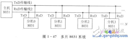
For the extension-to-host communication, one-to-one communication can be used for each extension to the host. This approach greatly increases the host's serial interface circuitry and transmission cable. If the structure shown in Figure 1-47 is used, the outputs of the extensions O to N are connected in series, which will cause the signal on the transmission line 2 to be disordered, and even the serial output port of the extension will be burned.
In addition, with TTL level communication, the transmission distance is only a few meters; if RS-232C is used, the transmission distance is only a few tens of meters, which is less than the transmission requirement within 10 km.
In order to solve the above problems, we propose a bus-type serial transmission mode: the three-state gate is used to realize the isolation of the transmission line 2 from the uncommunicated extension, and the serial signal transmitted on the transmission line is the modulated -12~+12 V square wave signal. The transmitter and the receiver use a current loop to implement communication transmission.
Set the master and extension communication baud rate to 600 b / s, the serial signal is: O level modulation into 1 200 Hz, l level modulation into 2400 Hz -12 ~ +12 V square wave signal. The main and extension communication circuits are identical.
1. Hardware circuit
The communication system hardware circuit is shown in Figure 1-48. In the figure, when the logic of point A is 1, the modulator is turned on, and the signal of point B is transmitted to the transmission line 2; when the logic of point A is 0, the modulator is locked, and the serial output port is in a high impedance state.
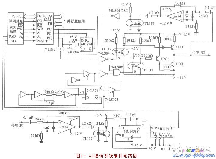
To start the serial port occupying the transmission line 2, first check the transmission line status, that is, let PC0 = 1, PC1 sends a negative pulse "U" clear 74LS74 Q end is 0; after waiting time t2, check PC4. If PC4 is high, it means that the existing extension occupies the transmission line 2, and at this time, the data cannot be transmitted to the transmission line 2. Even if data is transmitted, since Q = 1, the serial port is locked, and data cannot be sent to the transmission line 2. If PC4 is low, the transmission line 2 is idle, and the 8031 ​​control 8255 sets PCo to o, and the modulator is turned on. Since the U1 terminal is at a low level, the signal on the transmission line 2 cannot cause the 74LS74 CP terminal to be flipped from 0 to 1, and the 74LS74 Q terminal is always at a low level, and the extension occupies the transmission line 2.
After the extension has sent the data, set PCo to 1 to lock the modulator.
2. Communication software
When the host sends a call to each extension through the transmission line 1, the data RB8=1; otherwise RB8=0. The host calls the extension signal as defined below:
When SD7 =1, the host pair extension number is SD6~SD. The extension sends a call, and then the next byte (RB8 -O) sends a command (registration, control, consultation, etc.) to the extension. After the extension receives the command, it sends data to the host and answers the host.
When SD7=0, the host has no call to any extension, SD6=SD. Invalid, each extension can place a call to the host to implement the call of the extension-host. In order to prevent two or more extensions from making calls to the host at the same time, each extension uses this data as a synchronization signal, starting from the time when the byte is received, and delay time according to the extension number. , then check transmission line 2 and start sending.
Transmission line 2 is open to an extension.
Check the status of transmission line 2, ie PC, send "U", delay t2 ("111 200 s). The 74LS74 Q terminal can accurately reflect the state of the transmission line 2.
Check PC4. If it is low, it can start sending. If it is high, it means that there is data transmission on transmission line 2, it can't start sending, and then try to start when the next sync signal arrives.
When the extension uses the serial port, let the PC. =1, the modulator is turned off, so that the serial port output is in a high impedance state.
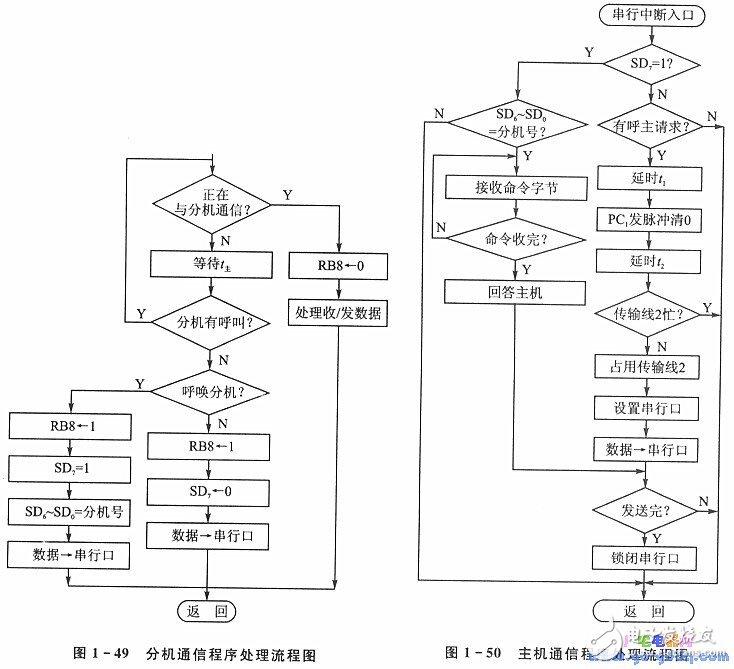
The processing flow of the main and extension communication programs is shown in Figure 1-49 and Figure 1-50. In Figure 1-49, t is the delay wait time for the host to send a synchronization signal to the extension continuously, waiting for the extension to respond to the last synchronization signal sent by the host.
t main = ll / 600 + t + 2 [t + 1] max + tD where: tD is the redundancy time.
The bus serial communication method proposed in this section is applicable to distributed multi-machine systems with less data transmission. Up to 27 extensions can be connected to a single host. In the case that the number of connected extensions is small, the high-order data of the host call extension signal can be defined as some common commands to reduce the transmission of the host-extension command byte and increase the transmission rate.
The transmission method has been tested in a multi-machine distributed warning system and proved to be feasible.
Mini Box,Intel Celeron Processor Mini Pc,Customizable Pc,Mini Pc Desktop
C&Q Technology (Guangzhou) Co.,Ltd. , https://www.gzcqteq.com