Low-voltage AC lighting systems are becoming more and more popular in the market, from indoor accent lighting (Accent LighTIng) to general track lights, and even applied to outdoor lighting systems. Retailers and home building materials companies such as IKEA and Home Depot have quickly and widely communicated these technologies to customers, and included power supply systems in specific low-voltage usage rules, so users can install them without going through a contractor.
The rise of low-voltage AC LED lighting applications
All low-voltage AC lighting systems use an independent main power supply. This main power supply provides a solution for converting offline AC to low voltage. Under any load, even if the circuit is open, its output will not exceed 30 volts. Value (VRMS). Second, under all conditions, the circuit must have a current limit of 25 amps (A). These two conditions will determine the maximum power for low-voltage AC lighting applications. The typical output voltage is 12 or 24 volts alternating current (VAC), but the maximum current value of 25 amps must be maintained, whether it is a 12 volt, 300 watt (W) system or a 24 volt 600 watt system.
In view of the above-mentioned factors, low-voltage AC lighting is very popular in light-emitting diode (LED) lighting applications. This technology can even be applied to 300-watt LED lighting power, which is equivalent to the output of three to four street lights. This gives designers a great deal of flexibility in design, allowing relatively large single components or multi-configuration lamp designs provided by a single power supply, or designs in between. What is certain is that through the flexible LED lighting application design, the lighting system will move forward from the traditional incandescent lamp.
In low-voltage AC systems, three different lighting fixtures can be considered. First, only one or two individual systems are equipped with a large / high output design; secondly, they can support ten to twenty devices in the system's small light source. Medium-sized output design; finally, a small output design that allows fifty to one hundred luminaires in a single system.
Large array design creates high lamp output applications
In terms of large array design, in two different areas, the benefits of the unique LED design can be immediately displayed, especially in the more unique example of large lighting sources, high light source output can be created through the large array application. Generally speaking, 100-watt LED light sources will be used in street light applications (using high-voltage offline solutions), although it is not recommended to use low-voltage AC systems (this will bring new settings for the entire rules and standards), but Designers have the opportunity to achieve the same effect with a low-voltage alternating current budget, and then start designing with a 3.5 volt forward voltage and a standard LED that uses 350 milliamperes of current, roughly 1.2 watts or about eighty LEDs each. Based.
In order to achieve the desired output power, it is very attractive to use a single driver and use multiple sets of series / parallel combination LED schemes, but the industry generally discourages such design rules, because the support for individual control of each LED The first problem encountered by the circuit is that the LED and the temperature have a feedforward relationship. When the temperature rises, the forward voltage must be strictly controlled to avoid more current flow, which further increases the temperature of the LED. The biggest impact is that when different lines share the same current, the problem of improper matching will quickly occur. If the current is not arranged individually to pass through the entire line, it may become a source of system failure.
Use online design tools to find suitable LED drivers
As mentioned above, there are various drivers on the market that can meet the needs. National Semiconductor (NS) has several LED drivers that can achieve the maximum input range required, while also featuring simple design features and performance. Let's start with the 24VAC system, which is the most noticeable special large-scale lamp. The drivers we are talking about are all DC-DC converters, so there will be some AC signals provided by the main power supply. In the case of rectification, based on this situation, the input conditions for the converter must be changed to: 24VRMS = 67.88VPP and the maximum input voltage range of the driver after adjustment is 34 volts.
As far as the conditions are known, at this stage of the design, the designer may already have a specific LED specification in mind, and all the designs discussed in this article can be carried out using WEBEBCH LED Designer online design tools such as National Semiconductor For development, you can enter the input voltage (34 volts DC), LED type / value, and desired output configuration. In addition, under the conditions of 350 milliamperes and Vf = 3.5 volts, it can drive a 24VAC lamp string composed of nine LEDs, and the rectified is 34 volts direct current (VDC). The parameter search tool in the online tool seems to have many applicable input ranges. However, due to the limitation of the work cycle, there are actually not a large number of lines that can be supported. In this case, only National Semiconductor ’s LM3401 and LM3409 LED drivers can be supported. If the number of LEDs is reduced from nine to eight, the choice of drivers will increase.
It is worth noting that when the number of LEDs in the light string increases, it needs to be supported by boosting the voltage. The main converter topology for most low-voltage AC applications today is a buck converter (the driving voltage output to the LED is higher than the input The voltage of the converter is still low), which is the main point of view for fewer LED lines.
Understand driver role
In general, it is most cost-effective to use a single driver to drive multiple LEDs as much as possible. However, it is not recommended to use parallel lines in a single driver, but it is desirable to extend the series lines as much as possible; the advantage is that even if the lines are strictly regulated And protection, can also ensure that the current through the LED is the same. In this way, a large input voltage can simply drive a large number of LED lines, but after rectification, the line usually loses half of the AC voltage value, so its advantages are greatly reduced; to solve this problem, you can Switch to a boost solution (when the output voltage is greater than the input voltage) to reduce the burden of driving a large number of LED lines.
Another point of view is that if the light string can maintain less than twenty LEDs (Vf = 3.5V and 350mA LED drive current), the boost output can be maintained under the low voltage limit (under the low voltage limit of 84.85VPP 70VDC), which can be achieved by any LM342X driver of National Semiconductor. It provides overvoltage / undervoltage protection mechanism, current limit, and optional overheat protection according to needs.
In addition, the understanding of the characteristics of the driver device plays an important role in circuit design, such as whether it is necessary to support PWM dimming (PWM) dimming, analog dimming, etc., or whether to add some optical elements and change the light source output. Overheat protection, the above considerations are factors of which driver to choose.
In response to the above requirements, the LM3421 / 23 driver has the features to prevent and detect additional error warnings. It is a very suitable component for applications that want to achieve high-level protection and provide microcontroller (MCU) response. The built-in overheat protection function of the LM3424 is beneficial for optical or overheat protection applications (reducing the output current related to the LED temperature); in addition, although the LM3429 is the most basic driver for this series of products, it still has the Overvoltage protection and current limit to assist boost detection.
Figure 1 shows a circuit diagram for driving twenty LEDs, each with an average current of 350 milliamps and a 3.5 volt forward voltage. In addition, the circuit may require analog dimming (the output of the light source will decrease when the input decreases) Lower) and changed to conform to a simple and fully protected line driver. If you want to seek more strict color accuracy, you can use PWM dimming.
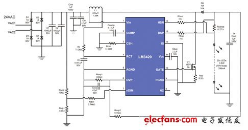
Figure 1 The large-scale array design uses the LM3429's boost configuration. It uses a 24VAC system and can drive twenty LEDs with a current of 350 milliamperes.
Large capacitance scheme reduces ripples and extends electrolyte capacitor life
A simple concept is to apply a boost solution to restore the voltage lost when driving a large number of LED strings with AC rectification, and still stay within the low voltage limit, which is about 27 watts consumed by the front end (24.5 at 92% efficiency) Watt LED), so it is obvious how the system can be expanded into a high-specification design where each line is fully protected under a single accessory.
If four such circuits are further used, each line can achieve the 100-watt design goal of complete protection and control. To achieve this architecture, a general rectifier may be used at the front end (only a bridge of & TImes; 4 current rate is required) Diode and C1 / C2 & TImes; 4 capacitor). In addition, if the LED lighting design has 300 to 600 watts of power available in a low-voltage system, the total current of 25 amps has many options for designers. For example, the headroom of the maximum voltage and current needs to be regulated from D1 to D4. The output capacitance can be expressed by the following equation:
C = 0.7 (I) / ΔE (f)
Among them, I represents the input current (DC to DC conversion area) to the downstream circuit, ΔE is the allowable ripple voltage, and f is the AC frequency. Since this design has 92% efficiency, given that the LED power is 24.5 watts, this means that the front-end DC-to-DC area will have 26.6 watts of power; and after rectification (34VDC), 26.6 watts will be used from the 24VAC power source and produce The average input current of 782 mA, so that the specifications of the diode rectifier can be adjusted appropriately.
On the other hand, acceptable ripple also affects the demand for capacitors. For example, implementing an input current of 800 milliamperes and allowing a 1 volt ripple on the 120Hz line (due to the bridge rectifier relationship 2 & TImes; 60Hz) requires a large capacitance of 9,300μF; if it is a 3 volt ripple, only 1,500μF is needed, because reducing the ripple provides better protection for the life of the electrolytic capacitor, so in this case, a large capacitance will be possible Options.
Small array design challenges are necessary to reduce the temperature of the capacitor is imperative
The other extreme design range is the small array design, which may be a single LED component or a single component containing three components, which can turn 1 watt into 3 watts. Modern LED lighting efficiency solutions, in the environment and Popular among park lighting equipment.
The small array design allows 105 ° C rated capacitors to be kept cool at 65 ° C and below, which is the weakest part of the design; however, because the electrolytic capacitor is 10 ° C below the rated temperature, it can The doubling of the service life means that if a designer can maintain a temperature condition of 65 ° C or better, the rated capacitance at 105 ° C will extend the rated life by 16 times. At this ratio, the rated capacitance of 5,000 hours It can be extended to 80,000 hours. Although it is a great challenge for small array design, it is still imperative.
This proves that good thermal design plays a key role in LED applications, and the use of efficient drivers such as the LM3429 makes design challenges easier to solve. In this design, the most popular device is a single-junction field-effect transistor (FET) M1 switch, which can reach a temperature performance of about 65 ℃, although it does not have much impact, but the designer must determine that it and other important heat sources are Keep a distance from the electrolytic capacitor, and keep all the components on the board below 50 ° C. It can be seen that the heat energy emitted from the LED is always the biggest challenge, not electronics.
ZGAR Vape Pods 5.0
ZGAR electronic cigarette uses high-tech R&D, food grade disposable pod device and high-quality raw material. All package designs are Original IP. Our designer team is from Hong Kong. We have very high requirements for product quality, flavors taste and packaging design. The E-liquid is imported, materials are food grade, and assembly plant is medical-grade dust-free workshops.
From production to packaging, the whole system of tracking, efficient and orderly process, achieving daily efficient output. WEIKA pays attention to the details of each process control. The first class dust-free production workshop has passed the GMP food and drug production standard certification, ensuring quality and safety. We choose the products with a traceability system, which can not only effectively track and trace all kinds of data, but also ensure good product quality.
We offer best price, high quality Pods, Pods Touch Screen, Empty Pod System, Pod Vape, Disposable Pod device, E-cigar, Vape Pods to all over the world.
Much Better Vaping Experience!


ZGAR Vape 5.0 Pods,ZGAR Vape Pods 5.0,ZGAR Vape Pods 5.0 Pod System Vape,ZGAR Vape Pods 5.0 Disposable Pod Vape Systems
Zgar International (M) SDN BHD , https://www.szdisposable-vape.com