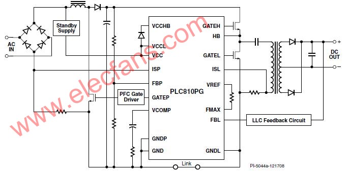
The PLC810PG combines PFC and LLC offline controllers with an integrated high voltage half-bridge driver. Figure 1 shows a schematic diagram of the power supply structure using the PLC810PG device.
The LLC resonant inductor is integrated in the transformer. The PFC portion of the PLC810PG uses a universal input continuous current mode (CCM) design that does not require a sinusoidal input input reference, thereby reducing system cost and external components.
The DC-DC controller drives the L LC resonant topology. This inverter controller can make
The MOSFET is switched at zero voltage, eliminating most of the switching losses and improving efficiency. At the heart of the LLC controller is a current controlled oscillator.
Its frequency control range supports the traditional operating frequency of TV power supplies.
To ensure zero voltage switching, the dead time of the LLC switch in the PLC810PG is tightly controlled within tolerance and can be adjusted with an external resistor. The duty cycles at both the high and low voltages are closely matched to provide a balanced output current, which reduces the cost of the output diode.
The typical PLC810PG LLC is designed to operate at 100 kHz (under rated operating conditions). Depending on the design of the LLC circuit, the switching frequency can vary from one-half to three times the rated operating frequency, which is related to input voltage and load variations.
This article refers to the address: http://
The frequency of the PFC converter is locked to the LLC to reduce noise and electromagnetic interference. Increasing the PFC frequency and LLC synchronization at light loads reduces the current when the PFC boost converter is switched to discontinuous mode, improving light load operation and reducing power line harmonics. The design also provides PFC and LLC primary side fault management.
The PFC PWM output phase can be dynamically adjusted based on the LLC phase so that the switching edges do not intersect the noise sensitive portions of the PWM and LLC timing circuits. Avoid edge collision techniques to simplify power distribution and improve performance. Phase synchronization can be reduced
Ripple current of EMI spectral components and PFC capacitors.
Optical Rotary Sensor,Custom Encoder,Optical Encoder 6Mm Shaft,Handwheel Pulse Generator
Jilin Lander Intelligent Technology Co., Ltd , https://www.jilinlandermotor.com