With the continuous development of ultrasonic technology, ultrasonic is widely used in the fields of detection, cleaning, welding, medical treatment, etc., and even in the textile and aerospace fields. At present, the research and application of ultrasound can be divided into two major fields of power ultrasound and detection ultrasound. Ultrasonic cleaning is one of the most widely used applications of power ultrasound. It converts the acoustic energy of power ultrasound into mechanical vibration through a transducer, while strong ultrasonic waves produce a "cavitation effect" when the liquid propagates. The shock wave emitted when the cavitation bubble suddenly closes can generate thousands of atmospheric pressures around it, and the direct repeated impact on the dirt layer, on the one hand, destroys the adsorption of the dirt and the surface of the cleaning member, and on the other hand, causes the dirt layer. The damage is removed from the surface of the cleaning member and dispersed into the cleaning liquid to remove impurities, dirt or greasy on the surface of the object. Compared with other cleaning, ultrasonic cleaning has the characteristics of high efficiency, low energy consumption, clean and environmental protection, especially when cleaning complex parts, blind holes and many slits.
1 Ultrasonic cleaning machine overall design
The ultrasonic cleaning machine designed in this paper is based on STC single-chip microcomputer, including rectification and filtering, inverter, IGBT drive, PWM generation and control, frequency sweep display, power adjustment, tuning matching and impedance matching module and related protection modules.
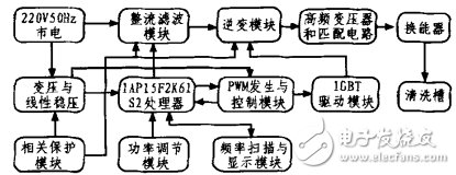
Figure 1 Block diagram of the ultrasonic cleaning machine
In the ultrasonic cleaning machine, the 220 V50 Hz mains input is divided into two ways, one for generating high-power ultrasonic waves and the other for detecting, controlling and displaying the power supply, as shown in Fig. 1. Among them, the power of the washing machine can be controlled by the two-way thyristor. The inverter module is a half-bridge inverter, which inverts the DC voltage into a high-frequency AC voltage, and then is tuned to match the transformer boost and impedance matching of the impedance matching module, and can be delivered to the piezoelectric transducer with high efficiency and maximum power. . Finally, the piezoelectric transducer converts the electrical energy output by the ultrasonic power source into high frequency mechanical vibration.
2 Ultrasonic cleaning machine module design principle
2.1 Rectifier Filtering and Power Conditioning Module
The 220 V50 Hz AC power is generated by the rectifier bridge B1 rectification and the electrolytic capacitor C12 to generate a DC output voltage. The two-way thyristor TR1 is used for power regulation, C11 is a safety capacitor, and R11 and C11 are mainly used to eliminate high-frequency interference. U1 is an optocoupler, the model can choose MOC3021, 1 foot and 3 feet to adjust the power module. The optocoupler U1 acts to isolate the strong and weak electricity, which enhances the reliability and safety of the circuit.
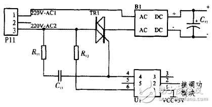
Figure 2 rectifier filter module
During the operation of the ultrasonic power system, the rectifier filter module and the inverter module will generate heat, and the two modules can be mounted on an aluminum heat sink for air cooling. In this way, the system can work safer and more reliably.
2.2 Inverter and pulse drive module
Because the half-bridge inverter circuit uses less power components, low cost, and relatively simple control, the ultrasonic cleaning machine designed in this paper uses a half-bridge inverter circuit.
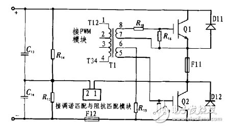
Figure 3 Half-bridge inverter module
In the half-bridge inverter circuit, two fully-controlled switching devices are IGBTs, that is, Q1 and Q2 and diodes D11 and D12 form a half-bridge inverter, and complementary signals are applied on Q1 and Q2, and O1 and Q2 are IGBTs in turn. Triggered, that is, each alternately conducts. At the same time, the capacitors C1 and C2 at the input of the DC side should be large enough, and C1=C2, and the capacitance value can be 2μF or more. Similarly, the resistors R14, R15 should also be large enough, and R14 = R15, the resistance value can be selected more than 100 kΩ. The fuses F11 and F12 are used to protect the switching tubes Q1 and Q2 from excessive current.
Transformer T1 and resistors R16, R17, R18, and R19 form a pulse drive module that provides complementary trigger signals for Q1 and Q2. Since the driving voltage of the IGBT should be less than 20 V, and the input voltage between T12 and T14 is about 12 V, the transformer T1 ratio is designed to be 1:1:1. R18 and R19 are used for current limiting, and about 20 Ω is optional. resistance. In the ultrasonic cleaning machine, the upper and lower IGBT devices have a certain dead time to prevent the two from being turned on at the same time.
2.3 Transformer and linear regulator
220 V50 Hz AC power is stepped down to 12 V via transformer T4, and then rectified by bridge rectifier B4, C41 filter and U1 (L7812) linear regulator, output 12 V DC voltage, power supply to PWM generation and control module. At the same time, the DC 12 V is re-regulated by U2 (L7805) to 5 V, which provides power for the processor IAP15F2K61S2. LED1 LED, which acts as a power indicator. In order to reduce the pulsation coefficient of the voltage, capacitors C43 and C44 are added for multiple filtering.

Figure 4 Buck and Linear Regulator
2.4 PWM generation and control module and driver module
In this ultrasonic cleaning machine, KA3525A is used as the PWM generation and control chip. As shown in Figure 5, the KA3525A oscillation frequency is set in the range of 20 to 40 kHz. A resistor Rd in series between pin 5 and pin 7 of the chip can adjust the dead time over a wide range. The oscillation frequency of the KA3525A can be expressed as:

Where: CT, RT are the capacitance and resistance of the oscillator connected to the foot 5 and the foot 6, respectively; Rd is the discharge end resistance connected to the foot 7. Here: Rd, CT, and RT are R52, C5, and (R51+Rp51) in the figure, respectively. Among them, Rp51 is a precision adjustable resistor, that is, the PWM output frequency can be adjusted by R1 and R2. Pin 8 is connected to a capacitor C51 for soft start, reducing the power-on impact of the power switch. The 11 and 14 feet output two complementary PWM waves, which are amplified by the medium power transistors Q1, Q2, Q3 and Q4, and then drive the two IGBTs through the pulse driving transformer T1 to control the inverter module to realize the half bridge inverter (Fig. 3) Shown). The high-frequency transformer T1 acts to isolate the strong and weak electricity, enhancing the drive capability and the reliability of the power supply.
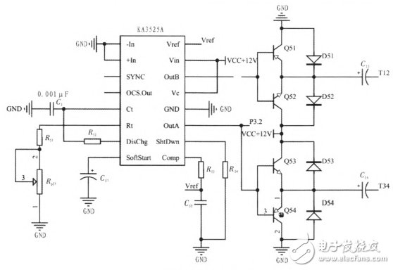
Figure 5 PWM Generation and Control Module
2.5 power conditioning module
Implementation principle of power adjustment: The voltage on the power-regulating resistor is detected by an AD port of the IAP15F2K61S2 microcontroller, and the AD value is obtained by analog-to-digital conversion. According to this value, the triac thyristor TR1 zero-cross delay trigger is controlled, that is, the output power is controlled by controlling the phase of the trigger pulse. Among them, Figure 6 is the zero-crossing trigger schematic diagram, 12 V AC through the diode D31, D32 rectification and R31, R32, R33 current limit voltage limit, and then through the transistor Q3 to detect the zero crossing. When the grid voltage crosses zero, P3.3 produces a negative pulse. In addition, the P3.3 port of the IAP15F2K61S2 microcontroller is an external interrupt port that obtains the zero-crossing of the power-frequency voltage by detecting the zero-crossing pulse.
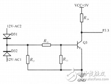
Figure 6 Zero-crossing trigger schematic
2.6 Tuning Matching and Impedance Matching Module
The matching of the ultrasonic power supply to the transducer is mainly tuning matching and impedance matching. In the tuning matching, in order to reduce the reactive power loss caused by the electrostatic reactance, the piezoelectric transducer outputs the maximum power, and the transducer needs to be approximated to the pure resistance state by matching, thereby improving the output efficiency of the ultrasonic power source. In addition, if the tuning is completed, that is, when the load is in the pure resistance state, in order to make the power supply output the maximum power, the actual load and the optimal output impedance of the power supply need to be equal, and the implementation method is as follows: the transducer is made by the high frequency transformer. The impedance is converted to the optimum output impedance of the ultrasonic power source, thereby allowing the piezoelectric transducer to output maximum power.
Figure 7 shows the ultrasonic cleaning machine tuning matching and impedance matching module. Among them, the dotted line frame is the equivalent circuit diagram of the piezoelectric transducer.
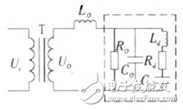
Figure 7 tuning match and impedance matching
Among them, Co is the static capacitance of the piezoelectric transducer, mainly the capacitance generated by clamping, it is a real electrical quantity; Ro is the dielectric loss resistance of the piezoelectric transducer, generally considered Ro infinity, usually Neglected; Ld, Cd, and Rd are the dynamic inductance, dynamic capacitance, and dynamic resistance of the piezoelectric transducer, respectively. When Ld and Cd are in resonance, the series branch is pure resistance. Under the series inductance tuning match, the entire load of the ultrasonic power supply exhibits pure resistance. When the output voltage of the power supply is stable, the power obtained on the resistive load is only related to the resistance of the load. Therefore, a high-frequency transformer is required for impedance conversion, so that the ultrasonic power source can output at maximum power.
3 Conclusion
According to the actual needs, the STC is a single-chip microcomputer with IAP15F2K61S2 as the control core, and the overall design scheme of the ultrasonic cleaning machine system is proposed. According to the design scheme, the software and hardware are designed and debugged to ensure that the working frequency is continuously adjustable in the range of 20~50 kHz, and the dead time is stable, so that it can be generated after matching with the ultrasonic power source and the piezoelectric transducer. Power ultrasonic. Finally, according to the design, an ultrasonic cleaning machine with power adjustment, frequency modulation and timing function was produced. Through field tests, the ultrasonic power supply system can work stably for a long time.
Power Lan Transformers For Automotive Product,Ferrite Core Pluse Transformer,High Power Pulse Transformer,Pulse Transformer Vs Power Transformer
IHUA INDUSTRIES CO.,LTD. , https://www.ihua-transformer.com