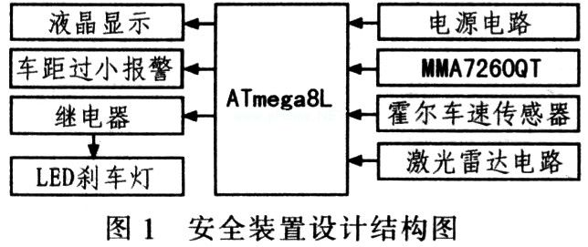
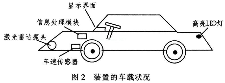
2 Safety device composition and hardware circuit design Safety device hardware circuit design is mainly composed of single-chip control, acceleration sensor, laser radar, LED brake light and power supply circuit, as shown in Figure 1, the vehicle status is shown in Figure 2.
This article refers to the address: http://
2.1 Microcontroller ATmega8L
   The design uses high-performance, low-power microcontroller ATmega8L, which is an 8-bit CMOS process microcontroller based on advanced AVR RISC architecture. The device integrates an analog comparator with 6 channels of 1O bits (8 channels in TOFP and MLF packages). A/D converter, 3 flexible timer/counters with compare mode, 512-byte EEPROM, on-chip/out-of-interrupt, 5 software-selectable sleep modes, and 8 KB of in-system programmable Flash Memory (programmable online) for easy product design and updates. At the same time, the ATmega8L achieves nearly 1 MIPS/MHz performance, runs 10 times faster than a typical CISC microcontroller, and the device is inexpensive, providing a flexible and low-cost solution for many embedded control applications. In addition, the ATmega8L operates from 2.7 to 5.5 V, making it ideal for applications where voltage fluctuations are high.
2.2 Acceleration sensor MMA7260QT and single-chip interface design The system design uses acceleration sensor MMA72600T to measure acceleration. The device uses MEMS principle to produce a low-cost, low-power, single-chip integrated XYZ three-axis inductive accelerometer that accurately measures dynamic or static accelerations from 0 to 350 Hz, ±6 g, and monitors small body vibrations. The tilt angle of the vehicle. The device integrates signal conditioning, single-pole low-pass filter and temperature compensation technology, and is available in 4 ranges (1.5g, 2g, 4g, 6g), 2.2~3.6V Power supply, operating current is less than 500μA, and the minimum supply current is only 3μA in sleep mode.
The MMA7260QT accelerometer collects vehicle acceleration data and transmits the data to the ATmega8L via the PD7 (AIN1) port of the ATmega8L. The specific connection circuit is shown in Figure 3.
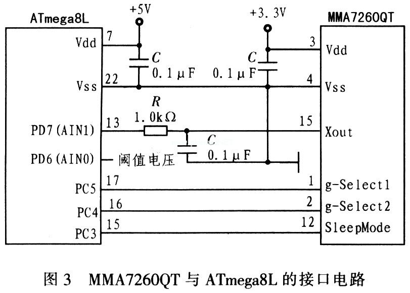
In Figure 3, when the Xout output and the threshold voltage are matched, the system issues an analog comparator interrupt, and the MCU turns to the LED brake light to flash the interrupt subroutine processing. This way, system resources can be saved. The RC between the Xout and PD7 pins has a filtering effect to reduce clock noise by adding a decoupling capacitor between the power supply and ground. In addition, the actual welding installation should ensure that the acceleration sensor MMA72600T is placed as close as possible to the microcontroller ATmega8L.
2.3 Hall speed sensor Hall speed sensor consists of 8 grade magnetic steel, UGN-3030T Hall switch sensor, LM2917 and amplifier circuit, as shown in Figure 4.
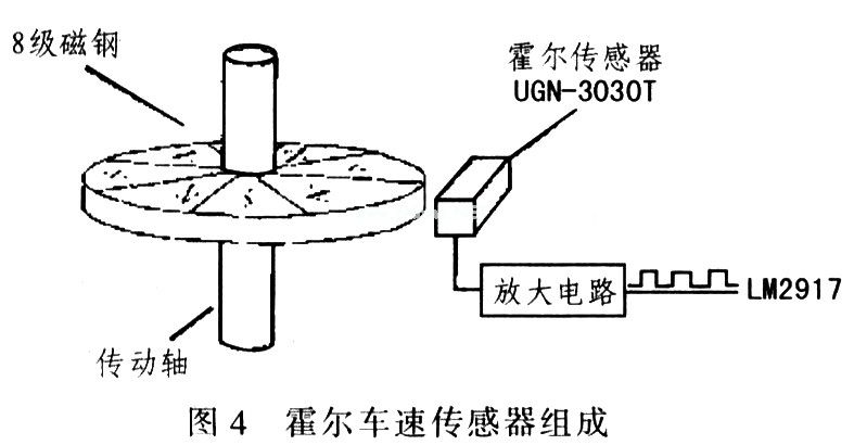
In Figure 4, the car transmission part drives the rotation of the 8th grade magnetic steel. Due to the change of the magnetic field, the Hall sensor generates 8 pulse signals per revolution of the 8th grade magnetic steel, and the output is processed by the amplifier to the frequency/voltage converter LM2917. The A/D converter measures the current vehicle speed based on the LM2917 output voltage.
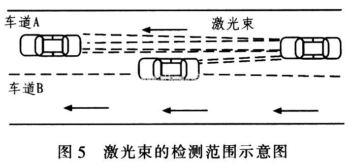
2.4 Lidar ranging ranging methods mainly include ultrasonic, laser radar, continuous wave radar, etc. Based on cost and design requirements, laser radar ranging is the best choice. Lidar ranging has two modes: continuous wave and pulse wave. This design uses pulse wave method. The safety device emits a pulsed infrared laser beam to illuminate the front side, and uses the reflected light of the rear reflective component (mainly the car number plate) of the automobile to detect the reflected light through the light receiving device, and the single chip calculates the distance according to the time difference.
The part of the circuit is composed of a light-emitting part, a light-receiving part, a signal conditioning circuit and the like, and the final output signal is processed by the system single-chip microcomputer. Since the laser beam is concentrated, a single launch mode cannot effectively detect a certain distance in front. Therefore, three laser radar ranging modules are installed in front of the car. If the distance detected by one of the modules is less than the minimum allowable distance at that time, the safety device will alarm. That is, the vehicle inserted into the traffic flow can be detected in time and alarmed, as shown in FIG.
2.5 LED Brake Light In this design, the brake light is composed of an array of light-emitting diodes. The light-emitting diode uses 1 W high-brightness LED produced by Evedight, and its response time is nanosecond, while the hot start time of ordinary light is about 250 ms. . Assuming that the car has a speed of 90 km/h (ie 25 m/s), the LED brake light that can be reacted quickly can issue a brake warning about 6 m ahead of time, thus effectively avoiding the rear-end collision of the car. Place the LEDs in the shape of three circles inside, inside and outside. When the MCU obtains the acceleration value exceeding the set threshold according to the input signal of the acceleration sensor, the output signal of the MCU is driven by the relay of ULN2003. After the LED brake lamp responds, it is illuminated by the inner one, the middle and the outer one, because of its high brightness and response. fast. It works well in actual use. In addition, this part of the circuit needs to be linked with the car brakes to ensure accurate output of the brake signal.
2.6 LCD display This design uses a parallel 128x64 LCD screen. Although it occupies more I/O ports, parallel transmission is convenient for writing drivers. If the system microcontroller cannot provide enough I/O ports, you can select serial data transmission. LCD. In addition, in order to allow the driver to more easily see the data measured by the design system, the display device should be placed in a reasonable position on the driver's console.
3 The system software design control part is controlled by ATmega8L. The main functions are: calculate the speed of the vehicle, the distance of the workshop, measure the acceleration, and display it in real time through the LCD; the actual workshop distance and the distance of the safety workshop will sound an alarm or the alarm light flashes; The acceleration of the time is compared with the set threshold to determine whether to illuminate the LED brake light. The system software design flow is shown in Figure 6.
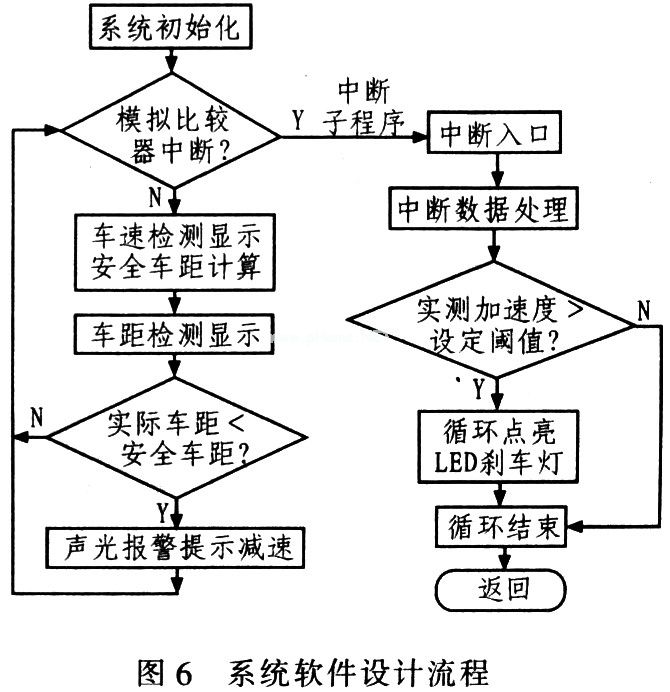
In the acceleration measurement, considering the vibration and noise during the driving of the car, the signal output is also required, and the necessary software filtering is also required. Here, the data average method is adopted. According to the "Regulations on the Implementation of the Road Traffic Safety Law of the People's Republic of China", the model of the relationship between safe driving distance and driving speed is as follows: when v≥100 km/h, S>100 m; when v<100 km/h, S>vt/ 1 000 m; where S is the safe driving distance, the unit is m; v is the vehicle speed, in km/h; t is hourly. S>50 m on the highway. The main software code of the software design is as follows:
Car_speed();//Car speed monitoring, return value i
Lcd_display(i,1);//The first line shows the car speed in real time car_distance();//the distance monitoring, the return value is j
Lcd_display(j,2);//The second line shows the distance car_cmpl(i,j) in real time.//Compare the distance between the vehicle and the safe distance to determine whether the alarm is #pragma interrupt_handler ana_comp_isr:17
Car_acc();//acceleration monitoring, return value is k
Car_cmp2(k);//Comparison of the actual acceleration and the set threshold to determine whether to illuminate the LED brake light. The main program is executed continuously after the vehicle is turned on until the vehicle power is turned off.
4 Conclusion The design uses functional modular technology, easy to operate and expand; select cost-effective devices, with good application and market prospects. The design scheme is practical and has great significance for car anti-tailing. In addition, the accelerometer used in the design can also be used as a vibration signal monitoring for car theft.
ECU Connector Section.
ECU-MEM-CONNECTOR is used to connect the ECU-MEM to the DIAG-LAYER. This part of ODX also links the ECU-MEM-objects with DIAG-COMMS e.g. used to read idents, download or upload the data. It allows an ECU to be flashed using ODX.
There are nearly 100 kinds of connectors used in general automobiles, and hundreds of connectors are used in a single vehicle model. With the increasing demand for automobile safety, environmental protection, comfort and intelligence, the application of automotive electronic products is increasing, which will make the number of Automotive Connector applications increase.
Four basic structural components of automobile connector
1. Contact
It is the core part of automobile connector to complete the electrical connection function. Generally, the contact pair is composed of positive contact and negative contact, and the electrical connection is completed by inserting the female and male contacts. The positive contact is a rigid part, and its shape is cylindrical (round pin), square cylinder (square pin) or flat (insert piece). The positive contact is generally made of brass and phosphor bronze.
The female contact, namely jack, is the key part of the contact pair. It relies on the elastic structure to produce elastic force due to elastic deformation when it is inserted with the pin, and forms a close contact with the positive contact to complete the connection. There are many kinds of Jack structures, such as cylinder type (split slot, shrink mouth), tuning fork type, cantilever beam type (longitudinal slot, 9-shaped), box type (square socket) and hyperboloid linear spring jack.
2. Shell
Also known as the shell, it is the cover of automobile connector, which provides mechanical protection for the built-in insulation mounting plate and pin, and provides the alignment of plug and socket when inserting, so as to fix the connector to the equipment.
3. Insulator
Insulator is also called automobile connector base or insert. Its function is to arrange the contact according to the required position and spacing, and to ensure the insulation performance between contacts and between contact and shell. Good insulation resistance, voltage resistance and machinability are the basic requirements for selecting insulating materials to be processed into insulators.
4. Annex
Accessories are divided into structural accessories and installation accessories. Structural accessories such as snap ring, locating key, locating pin, guide pin, connecting ring, cable clamp, sealing ring, sealing gasket, etc. Install accessories such as screws, nuts, screws, coils, etc. Most accessories have standard parts and general parts. It is these four basic structural components that enable the automotive connector to act as a bridge and operate stably.
Application characteristics of automotive connector
From the use purpose of the automobile connector, in order to ensure the better driving of the car, we can divide the reliability of the connector into the sealing property in use and the fireproof performance in the driving of the car. In addition, in the driving of the car, the connector can also show the shielding performance and temperature control performance. In general, when discussing the sealing property of automobile connector, the sealing performance of automobile connector is not only for water.
In this field, the current international management standard is IP67, which is also the highest level in the automotive closure industry. Although the waterproof requirements are different in different parts of the car, many automobile manufacturers will choose IP67 to ensure the airtight performance of their car connectors.
In the driving of the car, power supply is a very important energy source, not only related to the normal work of the engine, but also often involved in the use of power supply in the process of driving. Therefore, in the automotive power system, the automotive connector has different division, between the male connector and the equipment, between the male connector and the cable, between the male and female connector, and between the female connector and cable, there are certain sealing measures that can be implemented.
Sealing ring is a common tool in the sealing performance of automotive connector. This tool can not only achieve the effect of fixing between different hole positions, but also achieve the sealing effect. It can not only ensure the stable operation of automobile equipment, but also ensure the waterproof performance of automobile equipment in work. Most of the sealing rings are made of silicone rubber, which is made of liquid silicon and solid silicon after certain chemical changes.
Now the car is in use, electronic circuit technology is an important aspect of the automotive industry, not only in the driver's entertainment, but also in the driver's driving car control system, electronic circuit technology plays an important role in the stable work of the car. In order to ensure the stable work of electronic circuit technology, people have applied a lot of shielding technology in automobile production.
These shielding technologies not only play a protective role in the electronic circuit of the automobile, but also have the ability of anti-interference and anti radiation in the parts of the car. In addition, they can also play a protective role for the stable work of the automobile connector. These can be divided into two types of external shielding and internal shielding.
When using external shielding to protect automobile connector, two identical shielding shells are usually assembled together to form a shielding layer, and the length of the shielding layer can cover the whole length of the connector. On the shielding layer shell, there should be enough locking plate structure to ensure the reliable installation of the shielding layer. In addition, the shielding materials used should not only be treated by electroplating, but also be treated to prevent chemical corrosion.
The future trend of automotive connector
At present, the global automotive connector industry accounts for about 15% of the connector industry. In the future, it is expected to take a larger proportion under the drive of automotive electronic products. In terms of product cost structure, the average cost of connectors used in each car in China is only a few hundred yuan, compared with that of foreign countries
ECU Connector Section
ShenZhen Antenk Electronics Co,Ltd , https://www.antenkconn.com