introduction
This article refers to the address: http://
With the development of high-performance electronic display technology, the degree of electronic instrumentation is becoming higher and higher. High-tech products such as multi-function electronic display instruments, head-up display instruments, car navigation systems, and driving recorders have been developed at home and abroad. In the future, automotive electronic embedded instruments have the following advantages: providing a large amount of complex information, making the electronic control of automobiles more and more high; meeting the requirements of small size and light weight, making the limited driving space more humanized; The high reliability realizes the electronicization of the automobile instrument and reduces the incidence of the fault; the online fault diagnosis system is provided, and once the vehicle is faulty, the source of the fault can be found and the maintenance is convenient; the shape design freedom is high, and the automobile instrument panel is beautiful in appearance. Based on the above advantages, automobiles will increasingly adopt electronic instruments for various purposes. The embedded electronic instrument with novel shape and powerful function will be the development trend and trend of vehicle instrument in the future.
1 Intelligent vehicle instrument system structure
This smart on-board instrument has the functions of most traditional on-board instruments. The driver can obtain the current car status information such as vehicle speed, oil pressure, oil temperature, water temperature, oil pressure or battery power through the display interface of the vehicle instrument.
The traditional vehicle instrument is directly connected to the sensor of the vehicle, and the instrument system obtains the current state of the car through the analog quantity of the sensor, and the accuracy is not high. The intelligent vehicle instrument designed in this paper is not simply connected to the sensor, but the whole vehicle is connected into a network structure through the CAN controller. The vehicle components are equipped with a CAN controller, and the vehicle components are connected by twisted pairs to form a network system to realize the electronic components. At the same time, the electronicization of on-board instruments and automotive components also improves the accuracy and reliability of the car and reduces the incidence of failures.
The vehicle intelligent instrument is mainly divided into two parts: the hardware system based on S3C2440 processor and the software system based on WinCE environment. The hardware system provides the basis for the entire control system and is responsible for CAN bus communication. The software system provides hardware drivers for the CAN bus and instrumentation applications under WinCE.
2 hardware design
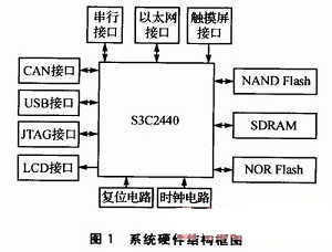
The hardware system takes S3C2440 as the core, RAM memory, NOR Flash and NAND Flash as storage medium, and expands some peripheral devices to be responsible for the input and output of system information, such as CAN bus communication unit, LCD display, touch screen, universal serial port, USB device. , Ethernet interface, etc. The system hardware structure is shown in Figure 1.
Among the many interfaces, the CAN bus communication unit is a key part in the vehicle communication process. In each important part of the car, the corresponding CAN control unit is configured, and the CAN bus control units are connected by twisted pairs. Each component of the vehicle is sent by the CAN control unit to the current state information of the component, and is sent to the CAN unit of the intelligent vehicle instrument via the twisted pair cable, and the data is sent to the system through the CAN interface of the system. After the vehicle instrument system obtains the data, the current state information of the automobile component is obtained through data processing.
The CAN bus interface circuit is shown in Figure 2. The chipbus controller MCP2515 from Microchip is used. The MCP2515 fully supports the CAN 2.OA/B specification and speeds up to 1 Mbps; the SPI interface standard makes it simpler to connect to the S3C2440; it can send and receive standard and extended data frames as well as remote frames; comes with 2 acceptance mask registers and Six acceptance filter registers can filter out unwanted messages, reducing microprocessor overhead. The CAN bus transceiver uses the TJA1050, which provides an interface between the CAN controller and the physical bus and differential transmit and receive functions for the CAN bus.
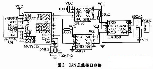
In order to enhance the anti-interference ability of the CAN bus node and improve the stability of the system, an optocoupler isolator 6N137 is added between the CAN controller and the CAN transceiver instead of directly connecting the TXCAN and RX-CAN terminals to the transceiver. Electrical isolation between the CAN nodes on the bus is achieved. At the same time, this also solves the problem of level compatibility between the MCP2515 and the TJA1050, and also suppresses spikes and noise interference in the CAN network. The two power supplies used in the optocoupler part of the circuit must be completely isolated, otherwise it loses its meaning. The isolation of the power supply can be achieved by using a low-power power isolation module or a switching power supply module with a 5 V isolated output. Although these parts increase the complexity of the interface circuit, they improve the stability and security of the node.
At the CAN interface, two 60Ω resistors (120 Ω total) on the CAN communication line are used to increase the load and reduce echo reflection. This is a remedy for impedance matching. A capacitor is connected between the two 60 Ω middle sections and the ground to prevent interference.
3 software design
The overall environment of the software is the winCE programming environment. The corresponding WinCE operating system is customized for the in-vehicle smart meter hardware system to realize the hardware driving. Then write the application, realize the operation of the system hardware by the specific operation of the application, that is, realize the function of the system. The key to this is the driver for the CAN controller. The CAN driver implements the operation of the application software to the CAN control unit and reads the data code in the CAN control unit.
Flame Retardant Cables
Standard applied: IEC60332
Rated Voltage: 450/750V 600/1000V
Insulation: LSOH (Low Smoke Zero Halogen)
Sheath: LSOH (Low Smoke Zero Halogen)
Applications: Those Electrical Wire suitable for power & lighting circuits and building wiring. Also suitable for use as an earth wire the internal wiring of appliances and apparatus.
Fire Resistant Cable,Fire Rated Cable,Fire Proof Cable,Fire Wire Cable
Shenzhen Bendakang Cables Holding Co., Ltd , https://www.bdkcables.com