In the design of switching power supply, the design of the starting circuit often affects the starting performance, conversion efficiency and stability under high temperature and high voltage full load. How does the ZLG Zhiyuan electronic switching power supply module design a stable, efficient and safe starting circuit?
The startup circuit provides energy to the system and poses a risk to the stability of the power supply due to its severe loss in extreme conditions. A good startup circuit only supplies energy to the power system when it is started, and stops when the system is running normally. So how can the startup circuit be safe and reliable and stop working after the output voltage is established? Let me discuss the startup circuit of the switching power supply with me!
First, start circuit design concept
The input voltage range of the DC-DC switching power supply is wide, and the power IC chip needs a stable operating voltage, so the starting circuit needs to provide a safe and stable starting voltage for the IC. As shown in Figure 1 below, it is mainly a simple starting circuit composed of a resistor and a voltage regulator. The power consumption of the startup circuit is large under normal operation, especially when the switching power supply is in a high temperature environment, input high voltage, and output full load. Severe and easy to bring risks to the stability of the system, but also reduce the conversion efficiency of the switching power supply.
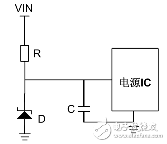
Figure 1 simple start circuit
Therefore, the startup circuit is not suitable for providing power to the power IC and the protection circuit for a long time, and generally only provides energy at the time of system startup. When the output voltage is established, the auxiliary windings with less loss provide energy for the chip and the protection circuit, and the startup circuit at this time needs to stop working.
Second, the common startup circuit design
As shown in Figure 2 below, it is a commonly used startup circuit in switching power supply. This circuit uses two triodes for secondary amplification, which can be equivalent to a three-terminal linear regulated power supply. It has fast startup speed, safe and reliable performance, and output voltage is established. The advantage of stopping work immediately afterwards.
The input voltage VIN provides the IB current for the NPN transistor Q1. It is in the amplification region. The IC is the amplification current and the base of the PNP transistor Q2. By controlling the IC current, the Q2 can be saturated and the saturation current of the IE is used. C charge until Q2 is in a half-cut or half-saturated state. At this time, the capacitor is equivalent to a constant current source to supply energy to the IC chip. When the capacitor voltage drops to a certain value, the starting circuit continues to charge the capacitor until the auxiliary power supply has a voltage, and then passes between the resistors R2 and R3. The voltage division causes Q1 to be in an off state, at which point the startup circuit stops working, and then the power supply to the chip is completely provided by the auxiliary winding.
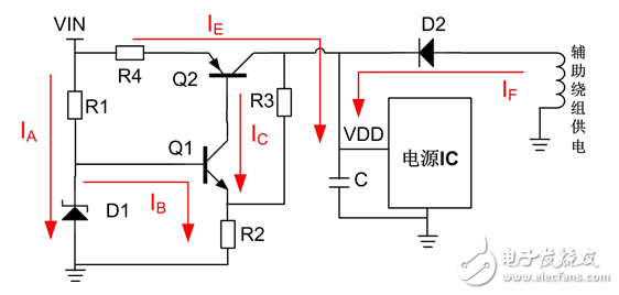
Figure 2 standard startup circuit
As shown in Figure 3 below, the experimental waveform of the circuit of Figure 2, green is the IE current waveform, yellow is the VDD voltage waveform (the oscilloscope uses zlgZDS2022). It can be seen from the figure that the switching power supply can be started in three stages. In the first stage, the IE charges the capacitor C with a current of approximately 1 mA during the power-on, and enters the second phase when the VDD voltage reaches the UCC28C40 threshold voltage. Increase to 5mA, continue to charge the capacitor while powering the IC. When the output voltage is established, it enters the third stage. At this time, the IE current is zero, the startup circuit stops working, and the VDD voltage rises to the auxiliary winding voltage. During the whole process of starting, the current of IE is relatively small and relatively flat, so the circuit is safe and reliable.
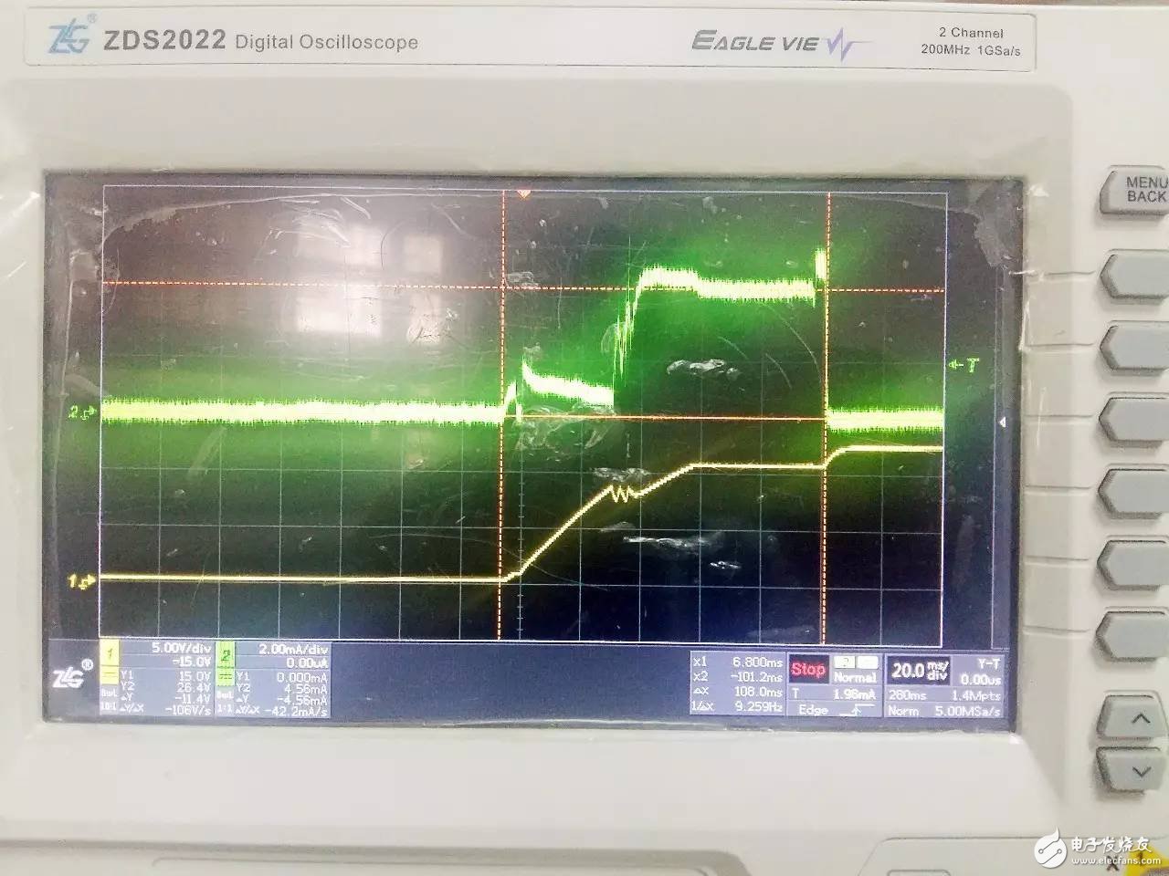
Figure 3 Experimental circuit waveform
Third, how to make the startup circuit safe and reliable
In order for the startup circuit to operate safely and reliably, in addition to the necessary theoretical calculations, more attention should be paid to the choice of the device. Careful device selection can bring the true value of the circuit closer to the theoretical value of the calculation. The Zener diode D1 should select a small dynamic resistance and a low knee point, so that the potential of the base of Q1 maintains a small fluctuation under a large change of the input voltage, thereby making the supply voltage VDD stable. The resistance values ​​of the resistors R1, R2, and R3 are as large as possible under normal operation of the circuit to reduce the loss of the startup circuit. R4 mainly limits the IE current so that Q2 quickly reaches the saturation point. If the condition allows the Q2 package to be as large as possible to enhance the heat dissipation capability.
The voltage of the auxiliary winding is also a factor affecting the stability of the starting circuit. If the auxiliary winding voltage is low, the starting circuit will not be completely cut off when the switching power supply is loaded. The Q2 tube may be burnt due to overheating under high temperature and high voltage full load. The auxiliary winding voltage is too high. Under certain abnormal conditions, the voltage supplied by the auxiliary winding approaches or exceeds the rated voltage of the power IC, posing a threat to the power IC. Excessive voltage on the auxiliary winding also has an effect on the overall efficiency of the switching power supply.
Choose high-quality isolated power modules to make circuit design more efficient
The isolated power supply module independently developed and produced by Zhiyuan Electronics has a wide input voltage range and is isolated from 1000VDC, 1500VDC and 3000VDC series. It has various package types and is compatible with international standard SIP, DIP and other packages. It can also be provided according to the special conditions of the project. Tailor-made tailor-made services, custom-made features, special packaged isolated power supply.
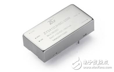
Zhiyuan electronic power module is widely used in power supply and industrial automation because of its high efficiency, wide input voltage range, small size, high reliability, good impact resistance, good isolation and wide temperature range. , communications, medical, transportation, building automation, instrumentation and automotive electronics.
This is a special TP008-600 electronic cigarette product series. We sell Tovapo TP008-600 vape pen disposable,TP008-600 vape pen kit,
TP008-600 vape starter kit, and other Tovapo vapes.
We are specialized electronic cigarette manufacturers from China, Vapes For Smoking, Vape Pen Kits suppliers/factory, wholesale high-quality
products of Modern E-Cigarette R & D and manufacturing, we have the perfect after-sales service and technical support. Look forward to
your cooperation!
TP008-600 vape pen disposable,TP008-600 vape pen kit,TP008-600 vape starter kit,400 mah vape kit,400 mah vape not charging
Ningbo Autrends International Trade Co.,Ltd. , https://www.mosvapor.com