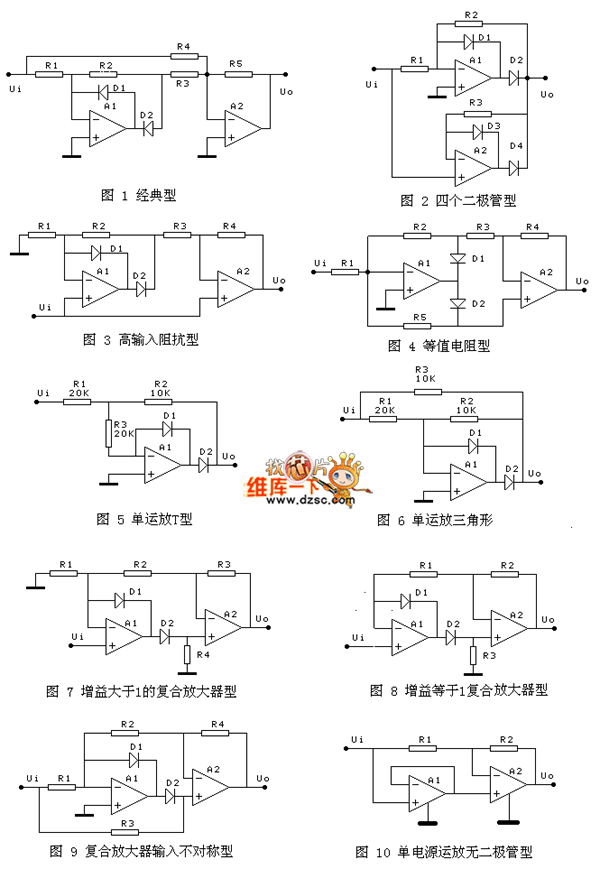
The name of the precision full-wave rectification circuit in the figure is purely his own name, just to distinguish; unless otherwise specified, the gain is designed according to 1.
Figure 1 is the most classic circuit, the advantage is that the filter capacitor can be connected in parallel with resistor R5. The resistance matching relationship is R1=R2, R4=R5=2R3; the gain can be adjusted by changing R5
The advantage of Figure 2 is that the matching resistance is small, only R1=R2 is required.
The advantage of Figure 3 is that the input is high impedance. The matching resistor requires R1=R2 and R4=2R3.
The matching resistors of Figure 4 are all equal, and the gain can also be changed by changing the resistor R1. The disadvantage is that in the negative half of the input signal, the negative feedback of A1 consists of two paths, one of which is R5, the other is composed of the A2 of the op amp, and the disadvantage of the composite op amp.
Figure 5 and Figure 6 require R1=2R2=2R3 and a gain of 1/2. The disadvantage is that when the input signal is positive for half a cycle, the output impedance is relatively high, and it can be isolated by the non-inverting amplifier with an output gain of 2. Another disadvantage is that the input impedances of the positive half cycle and the negative half cycle are not equal, and the internal resistance of the input signal is negligible.
Figure 7 positive half cycle, D2 pass, gain = 1 + (R2+R3) / R1; negative half cycle gain = -R3 / R2; the absolute value of the positive and negative half cycle gain is equal, for example, the gain is 2, you can choose R1 = 30K, R2=10K, R3=20K
The resistance matching relationship of Figure 8 is R1=R2
Figure 9 requires R1 = R2, R4 can be used to adjust the gain, the gain is equal to 1 + R4 / R2; if R4 = 0, the gain is equal to 1; the disadvantage is that the input impedance of the positive and negative half waves is not equal, the internal resistance of the input signal is required Small, otherwise the output waveform is asymmetrical.
Figure 10 is a follower design of a single-supply operation with a single-supply operation. When the input signal is greater than 0, the output is a follower. When the input signal is less than 0, the output is 0. Be careful when using it. A single power supply operates with a non-linearity with very small signals. Moreover, the single supply follower is also non-linear at the input of a negative signal.
In the three circuits of Figure 7, 8, and 9. When the output of the op amp A1 is positive, the negative feedback of A1 is formed by a composite amplifier composed of diode D2 and op amp A2. Due to the compounding (product) of the two op amps, It is possible that the gain of the loop is too high and it is easy to generate oscillation.
Some of the precision full-wave circuits are not recorded. For example, the high-impedance type also has a non-inverting input terminal of A2 connected to the inverting input terminal of A1. In fact, like the principle of this high-impedance type, there is no special recording. Others use A1. The output is only connected to one diode, because A1 is in an open loop state when this diode is turned off.
in conclusion:
Although there are ten kinds of precision full-wave circuits here, careful analysis shows that there are not many excellent ones. There are only three kinds of precision, which are the first three.
Although the classic circuit of Figure 1 has many matching resistors, it can be implemented with six equivalent resistors R, where resistor R3 can be connected in parallel with two Rs. The gain can be adjusted by R5, the gain can be greater than 1, or less than 1. The most advantageous is that it can be capacitively filtered on R5.
The advantage of the circuit of Figure 2 is that there is less matching resistance, as long as a pair of matching resistors is sufficient.
The advantage of Figure 3 is the high input impedance.
Others, some in the half cycle of D2 conduction, through the composite of A2 to achieve A1 negative feedback, for some op amps will appear self-excited. Some of the two half-waves have different input impedances and require a higher signal source.
Although the two single op amp types can achieve the purpose of rectification, the input and output characteristics are very poor. Both input and output are required to be isolated by a follower or a non-inverting amplifier.
Each circuit has its own design features, and we hope that we can draw on the useful design of its circuit. For example, the design of single-supply full-wave circuits and the design of composite feedback circuits are useful design ideas and methods. If you can analyze the circuit principles of each graph and derive each formula, you will benefit.
The final conclusion is for everyone's reference in circuit design.

MTU Gas Generator Powered by MTU gas engine, alternator, radiator, controller, base frame;
. World Famous diesel engine brand: MTU Gas engine
. World famous AC alternator brand: Stamford, Leroy Somer, Mecc Alte, Marathon, Faraday, SWT
. World famous genset controller brand: Deepsea, ComAp, Deif, SmartGen, Motortech
. Gas Control System: Ignition system, Gas Throttle System, Ga Mixer System, Gas Train Valve System
. Start Battery system
. Optional for Remote Cooling system with CHP & CCHP Control
. CHP- Combine with Heat and Power Electrical system
.CCHP- Combine with Cold, Heat and Power electrical system
Gas Engine,Mtu Gas Genset,Mtu Gas Generator,Mtu Biogas Generato
Guangdong Superwatt Power Equipment Co., Ltd , https://www.swtgenset.com