The use of XILINX's Spartan6 chip is also a matter of the last six months. Due to the short time to market, the chip users share less experience when using the chip; coupled with the first development and use of it, the development process will certainly encounter many difficult problems. It can be said that the users of the Spartan6 chip love and hate it!
1. The Spartan6 chip has a lot of clock resources, and there are many changes in the game rules for using it. XILINX provides a document on the Spartan6 chip, the Xilinx UG382 Spartan-6 FPGA Clocking Resources User Guide, which provides detailed instructions and analysis.
This article is to condense the article and re-interpret several key questions in a graphical way.
1. Find out which clock resources and clock BUFFER resources are currently available from Spartan6.
2. Find out the input and output of various clock BUFFER. This is the most important because these resources have a hard requirement for where the signal comes from, where it goes, and which objects to use.
The following paragraph is the rules for the use of various clock BUFFER provided by XILINX. Be sure to understand these words. The first reason is that it provides the type of clock BUFFER; second, it defines the input and output of various clock BUFFER.
Understand the use of each clock buffer type and how they can work best for your design
1. BUFG/BUFGMUX – Global Clock; Clock of Fabric; legal support for IDDR2, ODDR2 clocking.
2. BUFH – Increases number or global clock rouTIng resources; CMT outputs if BUFG's not used.
3. BUFIO2 – High speed clocking of IOSERDES/IOLOGIC (without DCM/PLL); Dedicated rouTIng to DCM/PLL/BUFG.
4. BUFPLL – SDR clocking of ISERDES2/OSERDES2.
5. BUFIO2FB – Dedicated rouTIng for feedback for DCM/PLL; GTP and PLL are
Also used to route through the BUFIO2FB.
To be honest, the first time I read this text, I still couldn’t figure it out, and I didn’t fully understand it. After reading, the layout of the clock resources in the chip cannot establish a clear picture. It doesn't matter, with the following figures, it will be easier to understand.
In the figure below, if the Spartan6 related materials are widely read, the following figures should be familiar. However, the amount of information contained in these figures is very large and worthy of being given out to everyone. These pictures can tell the user very well, where the input of the clock BUFFER comes from, and where to output it! ! ! !
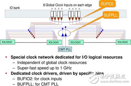
Figure 1 Diagram of BUFPLL and BUFIO2
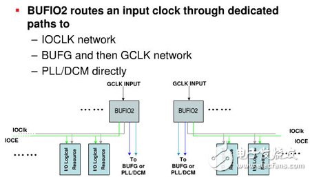
Figure 2 Detailed illustration of BUFIO2
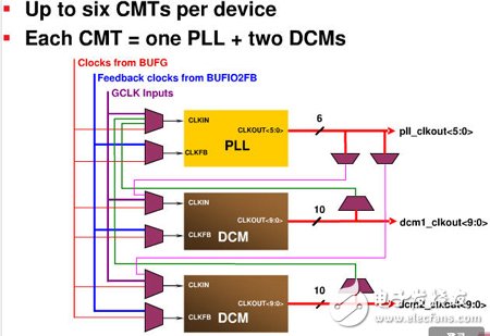
Figure 2 CMT input and output detailed illustration
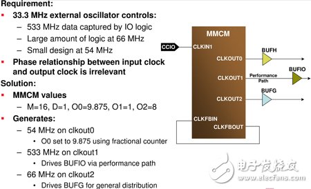
Figure 3 An example of a CMT use case
If you have read the above, look at Figure 4. If you can fully understand their relationship, it means that a clear picture of the clock resources has been established.
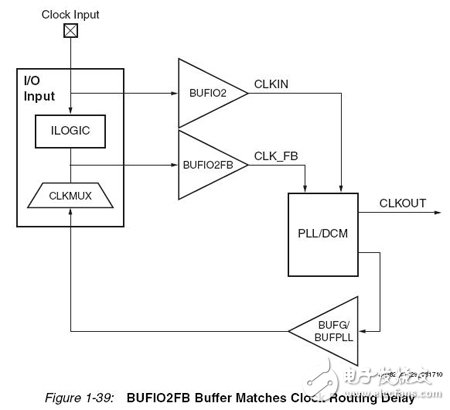
Figure 4 Spartan6 internal clock resource association diagram.
Give me a problem I encountered during the development process:
In my design, one of the BANKs has a system global clock input signal and a high-speed DDR input signal. Since the DDR input signal also requires an associated clock input, it is in the same BANK as the global clock input signal. My design terminates the associated clock signal through an instantiated BUFIO2 for the design code to use as the clock signal for the DDR module.
There was a problem in the MAP phase, and an ERROR report appeared. The report stated that my instantiated BUFIO2 could not be placed!!!!
I don't know why. At the beginning, the next step is painful debugging. . . (several wanted)
Later, after reading the following paragraph in Xilinx UG382, I realized how to solve it.
The FS Design When the CMT feedback path is used .
Ha ha. . . I know the reason why I wrote this blog post. I must figure out the clock resources of Spartan6! ! !
Female Header,Female Header Pitch 2.54Mm,Smt Female Header,In-Line Patch Female Connector
Shenzhen Jinyicheng Electronci Technology Co.,Ltd. , https://www.jycconnector.com