15w RF power amplifier The power amplifier can extend the power of power 1-2W, 88-108MHZ FM transmitter to 10-15W. It is composed of single-tube type-C amplifier and multi-stage low-pass filter. It has high conversion efficiency and strong achievements. Wave suppression ability. The circuit is shown in the drawing, using high-power transmitting tube C1972, its parameters are as follows: 175MHZ, 4A, 25W, power gain ≥8.5db, according to the parameters shown in the figure, the circuit working center frequency is about 98MHZ, input RF power about 2W , The rated output can reach 15W. In order to ensure that the output reaches the rated value at any frequency within 88 ~ 108MHZ, some components can be adjusted appropriately according to the center frequency of the previous stage. If necessary, the number of low-pass wave stages can be reduced to increase the output power. The expanded power signal is filtered by the three-stage low-pass filter to remove the higher-order spur components and fed into the transmitting antenna. When debugging the circuit, you must pay attention to the fact that due to the high power of the circuit, you must connect a dummy load (I use 30 1W, 1500Ω high-precision metal film resistors made in parallel), and there must be sufficient heat dissipation devices, and the power supply during normal operation is not Less than 2.5A, the antenna impedance is strictly equal to 50Ω, short rod rod antenna can not be used, otherwise the strong RF feedback current will cause the circuit to interfere with itself, most of the RF energy cannot be radiated into the space and is consumed on the power tube, causing overheating damage ; Must be led to the outdoor antenna for transmission through a 50Ω coaxial coaxial cable for transmission. The key to the normal operation of the circuit lies in the debugging of the circuit, and the whole process must be very careful. When debugging, only input a small excitation power, the power supply voltage drops to 9V, use a high-frequency voltmeter (can not use a general multimeter) to monitor the high-frequency voltage value at both ends of the dummy load, adjust C12, C14, L3, L4, L5, L6 1. Make the voltage amplitude reach about 15-20V, and then adjust C11 and L1 to make the voltage maximum. Then gradually increase the voltage. Each time the voltage is increased, C12, C14, C11, and L1 are adjusted repeatedly to make the output voltage the highest. Note that the voltage should be increased synchronously with the RF input excitation power to ensure the accuracy of the debugging results. When the rated value is reached, the working current is about 2A at a power supply voltage of 13.8V, the voltage at both ends of the 50Ω pure resistance dummy load is ≥40V, and the RF output power reaches 15W. Using this RF power amplifier with a 50Ω umbrella-shaped omnidirectional vertical transmitting antenna (gain of about 2dB), tested with a common FM radio, the transmission distance coverage is not less than 15K. |
 |

Follow WeChat

Download Audiophile APP

Follow the audiophile class
related suggestion
Avago Introduces New High Linear Power Amplifier Module Product Avago Technologies ...
The circuit is shown in Figure 1. The chip IC uses the LM1875 of the American NS company, which has a soft tone and low distortion (0.015% ...
The word "Monster" has both positive meaning and ...
When the output power of the digital power amplifier is greater than 50W, it is impossible to use only ...
If an "audiophile" is a group of people who are never satisfied with the sound and "loved the new and the old" with the audio equipment. Then just rely on these so-called "fever spirits" ...
First, the circuit principle and characteristics 1. Power amplifier part (see Figure 1)
There is a well-known saying in the Hi-Fi world that is "briefness first." This means that if ...
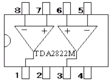
Simple and practical TDA2822M integrated power
TDA2030 is ...

STK465 thick film ...

This RF power amplifier can output 2-3 channel signals, covering an area of ​​about one square kilometer, is ...
![[Photo] Broadband high frequency power amplifier](http://i.bosscdn.com/blog/20/06/41/520536801.jpg)
Low frequency power amplifier
![[Photo] TDA2030 audio power amplifier](http://i.bosscdn.com/blog/20/06/41/5131012891.gif)
Looking at the Hi-Fi amplifiers currently on the market, the output power is 100W ...
![[Photo] Transistor 15W Class A Power Amplifier](http://i.bosscdn.com/blog/20/06/41/513102891.gif)
With the newly launched LM4651 and LM465 from National Semiconductor ...
![[Photo] 125W Class D Subwoofer Power Amplifier](http://i.bosscdn.com/blog/20/06/41/513100868.jpg)
![[Photo] Mark Levinson No. 30 ...](http://i.bosscdn.com/blog/20/06/41/513544752.jpg)
EL34 (6CA7) was first launched by Philips in 1956 ...
![[Photo] 45W transistor tube hybrid power amplifier](http://i.bosscdn.com/blog/20/06/41/513531952.jpg)
This article cleverly combines the electronic tube EL34 and the transistor (op amp), ...
![[Photo] 32W hybrid audio power amplifier](http://i.bosscdn.com/blog/20/06/41/513526493.jpg)
The pre-amplifier adopts a European-made TESLA brand low noise high cheek double transistor ...
![[Photo] Gallstone hybrid power amplifier using switching power supply](http://i.bosscdn.com/blog/20/06/41/513524776.gif)
"Simple" means the circuit of the amplifier is simple, making it easier, as long as the picture ...
![[Photo] Simple fool power amplifier](http://i.bosscdn.com/blog/20/06/41/513432946.jpg)
1. Description: & nb ...
![[Photo] LM386 low voltage audio power amplifier ...](http://i.bosscdn.com/blog/20/06/41/513417261.gif)
The Class A transistor power amplifier has a warm and sweet tone, which makes people tempted. But the temperature rise of Class A amplifier ...
![[Photo] Class A power amplifier using SAP15N / P audio pair tube ...](http://i.bosscdn.com/blog/20/06/41/513346769.gif)
The circuit is shown in Figure 5, ...
![[Photo] Using TDA7294 and 2SA1216 / 2S ...](http://i.bosscdn.com/blog/20/06/41/4233420295.gif)
'+ data.data.username +' '; dom + ='
In the outdoor lighting section, the global urban transformation, urban construction, residential construction and road construction for market demand of high-power, high-brightness, energy-saving LED driver power supply is extremely large. Isolated Programmable LED Driver no need of Optocoupler and side current control circuit to realize isolating constant-current output. The circuit structure is very simple.


The advantage of MOSO isolated programmable Industrial Light LED Driver is small
input/output capacitance, small output wave, isolated output, high power
factor, high current precision and high reliability. Fixed output Industrial Light power supply has output open-circuit
protection, over-voltage protection and short-circuit protection.
Dimmable Industrial Light LED Driver built in 2-in-1 dimming and auto-react:0-10Vdc, PWM signal, dali control is optional.
Architecture and industrial Light LED Driver adopt Soft-switching patented technology, high efficiency up to 93%.
Programmable High Bay LED Driver
Programmable High Bay LED Driver, Isolated Programmable LED Driver,Programmable LED Driver,Programmable High Bay Light LED Driver
Moso Electronics , https://www.mosoleddriver.com