ZigBee-based wireless temperature and humidity monitoring system for high-voltage switchgear
Introduction Important equipment such as busbar joints and outdoor knife gate switches in high-voltage switch cabinets of power plants and substations generate heat due to aging or excessive contact resistance during long-term operation. Because the temperature and humidity of these hot parts are not monitored in a timely and effective manner, it often leads to fires and large-scale power outages and other accidents. Real-time online monitoring of the temperature and humidity of the key parts such as bus bar joints and knife gate switches, to prevent the switch from overheating, can significantly reduce the occurrence of such accidents. In engineering practice, the joints in high-voltage high-current equipment have exposed high voltages, so the temperature and humidity of these parts are difficult to monitor. The usual temperature and humidity measurement methods cannot be used because they cannot solve the problem of high-voltage insulation.
At present, the methods for monitoring the temperature and humidity of the busbar joints in high-voltage high-current equipment mainly include infrared measurement, optical fiber measurement and wireless measurement. Optical fiber measurement technology uses optical fibers to transmit temperature and humidity signals. Optical fibers have excellent insulation properties and can isolate high voltages in switch cabinets. Therefore, they can accurately measure the operating temperature and humidity of high-voltage contacts and realize the operating temperature and humidity of contacts in high-voltage switch cabinets. Real-time online monitoring. However, the surface of the optical fiber used to isolate high voltages may be contaminated, leading to surface discharge of the optical fiber and cumbersome installation and wiring, which greatly reduces the reliability and range of use of the optical fiber measurement system. Infrared measurement is a non-contact measurement method without high-voltage insulation problems. However, it is easily interfered by the environment and the surrounding electromagnetic fields. The measurement accuracy is low and the degree of automation is low. It is often necessary to manually go to the high-voltage and high-current field test on a regular basis. The efficiency is low and the risk is high. In addition, the space in the switch cabinet is very small, and often it is impossible to install an infrared measuring probe (because the probe must maintain a certain safe distance from the measured object and need to face the surface of the measured object).
The wireless temperature and humidity monitoring system uses radio waves for signal transmission. The test module with sensors is installed on the surface of the high-voltage equipment and has no electrical connection with the receiving equipment. It fundamentally solves the problem of high-voltage insulation, has high measurement accuracy, and is easy to install. Not limited by the structure of the switch cabinet, it is an ideal solution for monitoring the temperature and humidity of high-voltage switch cabinets. The temperature and humidity monitoring system for high-voltage switchgear proposed in this paper is based on ZigBee, an emerging wireless network technology.
2 Realization of wireless temperature and humidity monitoring system for high-voltage switchgear
ZigBee wireless network technology is a short-range, low complexity, low data rate, low power consumption, low cost two-way wireless communication technology, its data transmission rate is between 10 ~ 250 kb / s, between two network nodes The single-hop distance is 10 ~ 75 m, the RF transmission power is low, and the processor supports multiple sleep modes. A lithium battery of ordinary capacity can guarantee the normal operation of network nodes for 1 to 3 years. The cost is low. The capacity of network nodes is large. It has self-organizing network, automatic routing and self-healing functions. It is an ideal solution to realize the wireless temperature and humidity monitoring system of high-voltage switchgear.
2.1 Hardware design
The hardware design of the network node of the wireless temperature and humidity monitoring system of the high-voltage switchgear proposed in this paper is based on the CC2430 chip launched by TI Company in accordance with the ZigBee technical standard. The schematic design of the RF part has been modified slightly based on the typical circuit. Considering that the system works in a high-voltage and high-current environment, in order to avoid leading high-voltage discharge, the network node uses a printed circuit board antenna or a ceramic antenna. ZigBee network includes 3 kinds of network equipments of coordinator, router and terminal node. The terminal node is equipped with a temperature and humidity sensor, which is the main sensing node and is placed in a high-voltage switch cabinet. Extra cables are often not allowed in the switch cabinet, and the terminal node supports the sleep mode, so it is powered by batteries. The coordinator and router nodes need to provide other network nodes with the function of routing and transmitting datagrams, so they use the mains power supply to make the coordinator and router nodes always work.
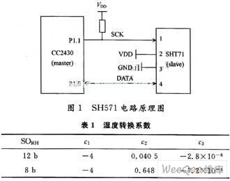
The temperature and humidity detection of the system adopts a new digital temperature and humidity sensor SHT71 based on CMOSens technology launched by Swiss SENSIRION company. It is a single-chip fully calibrated digital output sensor that integrates temperature and humidity sensors, signal amplification regulators, analog-to-digital converters and bus interfaces on a single chip, and can provide a resolution of 14 b in the range of -40 to 120 Temperature measurement and humidity measurement with a resolution of 12 b from 0 to 100%. SHT71 uses a serial interface to connect to the microprocessor. Its serial clock input line SCK and serial data line DATA are directly connected to the general purpose / output line of the microprocessor CC2430. The circuit schematic is shown in Figure 1. The serial clock input line SCK maintains communication synchronization with the microprocessor, and the serial data line DATA sends and receives communication protocol commands and data. The control flow is as follows: the microprocessor uses a set of "start transmission" timing to indicate the initialization of data transmission, then sends a set of measurement commands, releases the DATA data line, and waits for the SHT71 to pull down the DATA data line to low level, indicating that the measurement is completed. After the processor reads the measured value, the relative humidity and temperature values ​​can be calculated according to formula (1) and formula (2):
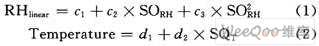
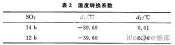
Equation (1) is the calculation formula of relative humidity, which is the humidity value read by the microprocessor. The parameter values ​​are shown in Table 1.
Equation (2) is the temperature calculation formula, which is the temperature value read by the microprocessor. The parameter values ​​are shown in Table 2.
2.2 Software design
The software design is based on Z-Stack 1.4.2, the latest version of the ZigBee protocol stack launched by T1. ZigBee network equipment can be divided into coordinator, router and terminal node according to different functions. After applying to join the network and becoming a child node of the coordinator or router, the terminal node can actively send datagrams to any node in the network, and can also ask its parent node whether there are datagrams sent to it and receive them. The router contains all the functions of the terminal node. In addition, it can be used as a parent node to allow other nodes to join the network, route and forward datagrams to other nodes in the network, assign logical network addresses, maintain neighbor device tables, and so on. In addition to all the functions of the router, the coordinator also includes the function of creating a new network. The process of creating a new network is shown in Figure 2.
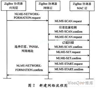
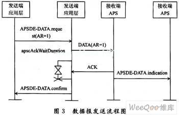
The coordinator initiates a new network establishment process through the NLME-NETWORK-FORMA-TION.request primitive. The network layer then requests the MAC layer to perform an energy detection scan on the channel specified by the protocol or the effective channel defaulted by the physical layer to detect possible interference. After receiving the successful energy detection scan result, the network layer sorts the measured energy values ​​in an incremental manner, and discards those channels whose energy values ​​are outside the allowable range. If the network layer finds a suitable channel, select a PAN identifier for the newly created network, and then select 0x0000 as the network address of the coordinator. After the network layer selects the network address, the ZigBee network creation process is completed by sending the MLME-START.request primitive to the MAC layer. ZigBee network supports three network structures: star network, cluster network and mesh network, in which any two network nodes in the mesh network can communicate with each other. The process of sending datagrams is shown in Figure 3.
2.3 Low power design
Because the high-voltage switchgear is a high-voltage, high-current environment, and it cannot be easily stopped once it starts working, the low power consumption characteristics of the terminal node, that is, the length of time that an ordinary lithium battery can maintain the normal operation of the terminal node is The key to determining the success or failure of the entire plan. TI's ZigBee solution ensures that ZigBee terminal nodes have good low power consumption characteristics from hardware and software. The ZigBee chip CC2430 is a system-on-a-chip in the true sense. It integrates the processor core, RF transceiver and various peripherals on a single silicon chip. Depending on the operating frequency and whether the peripherals are in working state, the CC2430 can work in PM0 , PM1, PM2 and PM3 four low power consumption modes, the current consumption is sequentially reduced, when working in PM3 mode, the current consumption can be as low as 0.6 A. The Z-Stack protocol stack also provides good support for low power consumption. The terminal node in the ZigBee network does not have a routing function. When it is in an idle state, its radio frequency part can be turned off, and the microprocessor can work in a low-power sleep mode. The datagrams sent to the terminal node by other nodes in the network can be stored in its parent node first. After each time the terminal node exits the sleep mode, it actively asks its parent node whether there is its datagram. The Z-Stack protocol stack supports two low-power implementations: LITE sleep and DEEP sleep. Among them, in LITE sleep mode, the terminal node can actively exit the low power consumption mode to complete tasks such as reading and sending sensor data; in DEEP sleep mode, the terminal node must be woken up by an external interrupt signal (such as a key event). According to the needs of actual engineering applications, the terminal node in the wireless temperature and humidity monitoring system of the high-voltage switchgear in this paper adopts LITE sleep low power consumption mode.
3 Field trial results
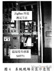
The temperature and humidity monitoring system based on ZigBee wireless network technology designed in this paper was tested on site in the capacitive high-voltage switchgear of the substation. The installation situation is shown in Figure 4. Each switch cabinet is equipped with 8 to 10 ZigBee terminal test nodes, which are used to test the temperature and humidity of switch contacts and busbar connection parts. All test nodes in the entire power distribution room form a ZigBee network through routing nodes. The terminal test node is in the dormant state most of the time. It wakes up every 5 minutes, reads the temperature and humidity value of the sensor, and sends it to the coordinator node in the ZigBee network. The coordinator can use multiple serial ports, Ethernet, or GPRS. Interface to send measurement data to the background management database. The system has been working normally for 10 months without changing the battery of the terminal node, and it is expected to work normally for more than 3 years.
4 Conclusion
Aiming at the urgency of temperature and humidity monitoring of the switch contacts and busbar connection of the high-voltage switchgear and the characteristics of the project site, a wireless temperature and humidity monitoring system based on ZigBee technology is proposed to achieve temperature and humidity monitoring at key points in the switchgear , Effectively preventing the occurrence of major accidents. The system has low implementation cost, easy installation, low power consumption of terminal nodes, stable operation, strong engineering practicability and market promotion value.
This is the most competitive 15.6 inch Budget Business Laptop, comes with 2022 intel latest celeron cpu-N5095, J4125, etc . Of course, other Budget Working Laptop are also available.
For example, 15.6 inch i5 4th Budget Workstation Laptop for your mid-level task, 14 inch i5 10th Budget Laptop For 3d Modeling, 15.6 inch i7 5th Budget Laptop For Photoshop, or 15.6 inch i7 10th budget laptop for work, etc. Of course, there are other type device, like Android Tablet, 2 In 1 Laptop , Mini PC , All In One PC.
A thin, portable, light-performance laptop may be the ideal tool when people choose a business laptop, therefore just ask yourself 1.what jobs you mainly need this device to do, then choose the cpu and storage necessary, 2.if need fingerprint or backlight; 3. prefer type C charging? Or traditional DC is ok? 4. Does RJ45 webcam is important for you? 5. how many hours you need the laptop to work when do your main jobs?
6.Camera position, prefer on the middle of screen up? or is ok on the bottom of screen?
Budget Business Laptop,Budget Working Laptop,Budget Workstation Laptop,Budget Laptop For 3d Modeling,Budget Laptop For Photoshop
Henan Shuyi Electronics Co., Ltd. , https://www.shuyioemminipc.com