Abstract: The anti-lost personal positioning system is developed by GPS/GSM technology. The system is used to search for and protect lost children or elderly people with intellectual disabilities. The system uses GPS positioning technology to obtain the position of the protected person, determine whether it is out of the safe area, and send its location information to the user through the GSM network. The user can set the working status of the system through the GSM network. The internal control of the system is completed by the single-chip microcomputer, which receives GPS data and commands from the user, and gives corresponding processing after analysis. The positioning accuracy of the system is within 10 meters, and the user can be notified of the position of the protected person in time.
Keywords: single chip microcomputer: global mobile communication system; global positioning system; TC35i
This article refers to the address: http://
0 Introduction With the improvement of people's living standards, wireless communication technology and global satellite positioning (GPS) technology are gradually applied to various fields of daily life. Whether it's anti-theft monitoring of cars or searching for and protecting lost children or elderly people with intellectual disabilities, wireless communication (GSM) and DGPS technologies all play an important role. The wireless communication method based on the GSM network has large coverage, good data confidentiality, convenient use, and low cost. Combined with the GPS system, the GSM system can transmit the location information of vehicles and personnel to the user's mobile phone through a wireless communication link, thereby realizing the monitoring of vehicles and personnel.
This design uses the GPS system to obtain the location of the lost child or the mentally handicapped elderly, and sends the location data to the user through the GSM network. Since the short message service is charged according to the number of sent short messages, as long as the short message is limited to 140 bytes each time, Yes, this data length is sufficient to transmit GPS location information. Protection of children and the elderly can be achieved in a cheap way. The system uses the widely used and inexpensive AT89C52 microcontroller, SIRF third generation GPS receiver module and GSM module TC35i design.
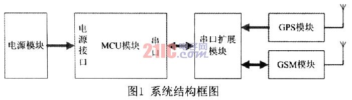
1 Personal positioning system hardware design The personal positioning system is mainly composed of four parts, namely GSM module, GPS receiver module, single-chip control circuit and power supply circuit. The GPS module is responsible for receiving the positioning data; the GSM module sends and receives short messages under the control of the single chip microcomputer; the single chip control circuit analyzes the GPS positioning data and makes corresponding processing according to the user's settings. The power supply circuit is generated by the 7805 and LM294lCS as +5V and +4.2v DC voltages, respectively. The +5V DC voltage is used as the working power supply of the single-chip microcomputer and the GPS module, and the +4.2V DC voltage is supplied to the GSM module. The structural block diagram of the system is shown in Figure 1.
1.1 Single-chip microcomputer control circuit The system uses the widely used AT89C52 single-chip microcomputer as the MCU. It has 8k bytes of Flash program memory and 1256 bytes of RAM inside. There is only one universal asynchronous serial port inside the microcontroller. In order to be able to communicate with GPS and GSM modules at the same time, the MCU needs two serial ports. Therefore, the system uses the serial port expansion chip GM8123 to simultaneously transmit and receive GPS data and GSM data. The interface circuit between the MCU and the GM8123 module is shown in Figure 2.
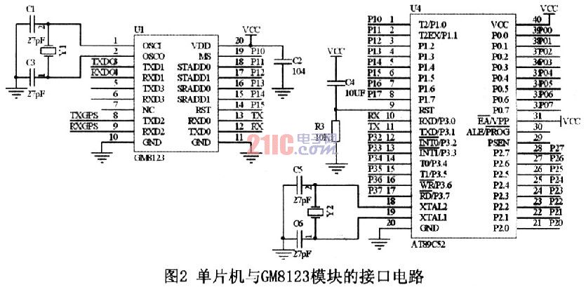
When the serial port expansion chip GM8123 is operating in multi-channel operation mode, the mode control pin MS=0. Multi-channel mode allows 3 sub-ports to work simultaneously at full duplex. In this working mode, the address lines STADD1 ~O of the chip are input ports, and the MCU controls the sub-serial port that wants to send data, and the address lines SRADD1 ~0 are output ports for returning the sub-serial port address of the received data to the MCU. Through the control of the chip, the single chip microcomputer can simultaneously communicate with the GPS module and the GSM module in full duplex.
1.2 GSM module The GSM module is responsible for transferring information between protected objects and monitored users. This system adopts GSM module TC35i of Siemens Industry of Germany. The TC35i module is an industrial grade GSM module that operates in the GSM900 and GSMl800 dual bands and supports Chinese short messages. The TC35i's data interface (CMOS level) transmits commands and data in both directions via the AT command. It supports SMS (short message) in Text and PDU formats. The GSM module interface circuit is shown in Figure 3.

1.3 GPS module The GPS module used in this system is SIRF third-generation high-sensitivity leaded GPS receiver module SIRF starIII. The chip has a positioning accuracy of less than 10m and can track up to 20 satellite channels at the same time. There is a rechargeable battery inside, which can store ephemeris data for quick positioning. The serial port data format is TTL level data output, the communication rate is 4800 communication baud rate, and the GPS full data is output once every second. The GPS antenna of the module adopts MMCX interface, the data line interface is 6-wire connector, and the cable output is simple to use. Generally, only three output lines are needed, and the first leg is connected with a DC positive power supply of 3.5 to 5.5V. The fifth foot is the power ground, and the second foot is the GPS output line. It is a TTL level serial port signal. The high level is greater than 2.4V, the low level is less than 0.4V, and the output drive capability is 2mA. Interface with the microcontroller. If only the default settings are used, the microcontroller only reads data from the module.
2 system software design
2.1 GPS positioning data reception default situation, GPS receiving module SIRF star III output positioning data once per second, usually using the $GPRMC streamlined data format, the data contains the longitude, latitude, speed (knot), direction of movement of the target Important information such as angle, year, month, hour, minute, second, millisecond, whether the positioning data is valid or invalid. The statement format is as follows:
$GPRMC, <1>, <2>, <3>, <4>, <5>, <6>, <7>, <8>, <9>, <10>,
Since only the location information needs to be known, it is only necessary to read <1> to <6> in the actual application.
<1>: Represents UTC local time. The format is "hours, minutes and seconds", and the hour, minute and second are both two.
<2>: Represents the working status. “A†indicates data is available, “V†indicates receiver alarm, and data is not available.
<3>: Represents latitude data. The format is "degrees. points."
<4>: Represents the latitude hemisphere, which is "N" or "S".
<5>: represents longitude data. The format is "degrees. points."
<6>: represents the longitude hemisphere, which is "E" or "W".
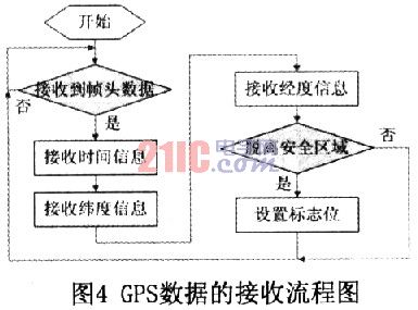
After reading the latitude and longitude data, the software analyzes the current location to determine whether the current location is in the security zone set by the user. The judging method is to calculate whether the safety activity radius exceeds a preset according to the latitude and longitude of the activity center point set by the user and the current latitude and longitude of the protected object. Set the corresponding flag according to the judgment result. The flow chart is shown in Figure 4.
2.2 GSM module control and short message processing MCU can control GSM module TC35i through AT command, send SMS common TEXT and PDU mode, use TEXT mode to send and receive SMS code is simple, it is very easy to implement, but the disadvantage is that it does not support Chinese SMS The PDU mode not only supports Chinese text messages, but also sends English text messages.
The choice of the two modes is determined by AT+CMGF. When AT+CMGF=0, it is PDU mode. When AT+CMGF=1, it is TEXT mode. When the message to be sent contains Chinese characters, the sending mode should be set first. In the PDU mode, the Chinese character is converted into a 16-bit Unicode code and then transmitted, and for the number, the 8-bit binary 0 is added before the ASCII code, and the 16-bit is sent and sent. When the mobile phone receives the short message, it determines whether the received short message has Chinese characters through the program, and then decides which mode to use to read the short message.
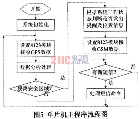
The MCU mainly transmits two types of information through the GSM module: one is to receive the user's settings and request commands, and to give a reply after processing; the other is when the MCU determines that the protected object leaves the security zone and sends a reminder to the user. And location information.
The format of user settings and request information is shown in Table 1. The main program flow chart of the microcontroller is shown in Figure 5.
When the user receives the location message, the location of the protected object can be determined. Users can query the geographic location of latitude and longitude data through Google Maps through a smartphone or computer.
3 Conclusion After testing, the system can achieve positioning within 10m accuracy, and can provide positioning services to users according to user settings. The system is easy to operate and is suitable for protecting the safety of mentally handicapped elderly and children, and has good practical value.
WARNING!
Do not plug two or more meters together!
IMPORTANT
Don't plug in an appliance where the load exceeds 16 Amp. Always ensure the plug of any appliance is fully inserted into the meter outlet. If cleaning of the meter is required, remove from mains power and wipe meter with a dry cloth.
KEYBOARD DEFINITION
1). SET: Set price with button UP.
2). MODE: Exchange display state.
3). UP: Set price combined with button SET.
GENERAL FEATURES
1).Display line power.
2).Display and memory accumulative total power quantity.
3).Display and memory total power charge of price.
THE DATA DISPLAY
Press MODE button the data displays as follows:
W →KWh →PRICE →COST/KWH
↑_ _ _ _ _ _ _ _ _ _ _ _ _ _ _ _↓
1). Plug in socket and power on, the meter will display real power.
2). Press MODE button once again and release, the meter will display accumulative KWh.
3). Press MODE button once again and release, the meter will display total power charge.
4). Press MODE button once again and release, the meter will display COST/KWH.
SETTING PRICE OF COST/KWH
1). Press SET button during display COST/KWH,the first digital COST/KWH flash, press UP button to set it.
2). Press SET button once again and release, the second digital COST/KWH flash, press UP button to set it.
3). Press SET button once again and release, the third COST/KWH flash, press UP button to set it.
4). Press SET button once again and release, the fourth COST/KWH flash, press UP button to set it.
5). Press SET button once again and release, the radix point COST/KWH flash, press UP button to set it.
DATA CLEAR
Press and hold MODE button for 5 seconds will clear KWH,PRICE and COST/KWH data.
Power Meter Plug Energy Monitor,Backlight Power Metering Socket,Blue Backlight Power Meter Socket,Multi-functional Backlight Power Meter Socket
NINGBO COWELL ELECTRONICS & TECHNOLOGY CO., LTD , https://www.cowellsockets.com