The basic rules for drawing a wiring diagram:
1. The wiring diagram is drawn according to the schematic diagram, so it must be wired according to the schematic diagram.
2. The components and models of the wiring diagram must be correct. The panel layout should be the same as that drawn on the panel layout drawing (note that the wiring diagram is the layout diagram behind the panel). The various components of the relay room should be arranged properly. Must have a certain overall situation.
3. Some components can only be connected to a single leg of a wire, such as: plug, socket, junction box, energy meter, and some of the comprehensive protection of the foot (specify the manufacturer).
4. The wiring diagram relates to the shielding line should indicate which line is the shielding line, which is the shielding layer, written next to the line or with a shield line symbol, for easy viewing.
5. For a line with two line numbers, it should indicate which cabinets use the first line number, and those cabinets use the next line number.
6. Don't miss the line. Check it after you draw it.
7. The layout of the components in the relay room should follow the wiring of the more components placed as close to the door hinges as possible. Similar components are arranged together. The placement of components will also affect the direction of the line.
Drawing wiring diagram process:
A, component layout
1. The arrangement of components on the panel from the perspective of the backsight is generally the heavier components such as the comprehensive protection near the door hinges, the following row is the indicator, the meter is a category, the bottom row is the control components, such as Buttons, knobs, switches, etc.
2. The layout of the relay room is divided into two parts, one is the terminal, and the lower part is the component board. If the components are less placed in a row, then the fuse, small open, etc. are placed on the leftmost (away hinge) Nearly), the relays are placed on the right, because there are many fuses and small open wires per unit area. If the components are relatively large, two rows must be placed, then the next one discharges the fuse, the small air opens, etc., to facilitate the operation, and the relay Wait on the top row. In general, the larger component is placed on the right side because it occupies the place.
3. Arrangement of terminals: The effective space for the 800mm-wide cabinet-mounted terminals is 650mm, which can be installed for 100 units for RUIZUBE RBT2.5. When there are more than two rows, the extra part is mounted on the component board. If there are many components on the component board, more terminals are installed on the side of the cabinet. The mounting method of the terminal is determined according to the secondary outlet hole, such as The outlet hole is close to the front door, then the test terminal is discharged below and the rest is placed in the top row.
4. The circuit breaker room is usually a socket and a heater, or a temperature and humidity controller sensor. The eVB, VB circuit breaker socket is 64 cores, and the rest of the circuit breaker sockets are 58 cores.
5. Cable rooms generally have CT, PT, heaters, lights, sensors, etc.
6. Handcart in addition to plugs, limit switches, sometimes isolated handcart and electromagnet. PT trolleys have PTs and sometimes counters.
7. The small bus may be at the top of the cabinet. It needs an exception to be drawn. If it is together with the terminal, it will be on the left side of the terminal. At this time, the small bus is generally a group of two terminals, and the group is separated from the group. Separated.
Summary: Generally a wiring diagram is so arranged that the placement of the components directly affects the direction and length of the line. It also affects the aesthetics and overall feel of the cabinet.
Second, the wiring diagram drawing
1. After the components are arranged well, you can start to write the corresponding code, panel A begins, relay room B, cable room C, circuit breaker room D, small bus E, PT, isolated handcart F. The model of the components is as complete as possible, and the same components must be written in full. For example, do not write the BBC small space into the BU251, and omit the specific current and AC and DC. If you do not write the whole, the assembly must be compared with the schematic, wasting time. There is a wiring diagram that draws as many components as possible and writes code numbers first. Then the code of the wiring diagram with few other components is used as an example. For example, an engineering comprehensive insurance is A1, sockets are all D1 and so on.
2. Drawing of components: components are drawn according to the actual object, some relays are embedded, or the wiring is before the board. At this time, the pin numbers of them are just opposite, and the drawing method and the physical object of the current transformer are the same, which improves the wiring. speed. What is more important is the comprehensive insurance, which is consistent with the physical quality of the painting.
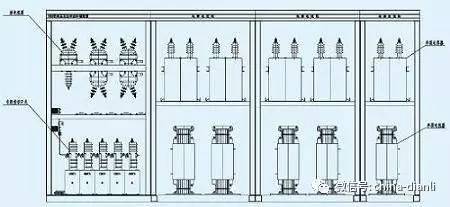
3. (Rear view) Take the outlet cabinet as an example. Panel connection: In general, the upper left corner shows the position of the trolley, the status of the circuit breaker, and the indication of the position of the grounding switch. The rest is generally divided into three rows, the top row is the comprehensive insurance, or the observation window of the power meter, etc. Among them is a row of various indicators, charged displays, etc. The following row is a variety of buttons, knobs, switches and so on. The specific traces are as follows: Remove the components from the overall protection, the first closest to the door hinge, and then the wiring in turn to the left, and finally connected to the top row of components (if there are other components), and then In the case of SGS, short-listed between SGS. There is no special case, the line on the panel can not be directly connected to the components on the board.
4. Wiring on the component board: The terminal is the component closest to the hinge of the door first, and then it is wired to the right in turn. Such as the general advanced fuse or small open, and then received relays. Note: Some components seem to be able to connect two wires, but actually only one wire can be connected. For example, the relay room light can only connect one wire because of its small pin.
5. The circuit of the circuit breaker room component is generally directly into the terminal.
6. The cable room CT, sensor, electromagnetic lock, etc. directly into the terminal. The main consideration is to connect the lamp and the heater. If the heater and the lamp are separated in the circuit, they are directly connected to the terminal. If there is a short wiring, then the first lighting, etc., is connected to the heater and then into the terminal.
7. PT, isolated trolley plug can only be connected to a line, S8, S9 limit switch can be connected to two lines, so there is a short line first on the limit switch shorted then re-plug. The pin numbers of the PT inlet plugs are 30, 31, and 33, respectively. . .
8. The terminal can connect two wires at most, and the terminal related to the lead wire should leave the upper end of the wire to facilitate the customer's wiring. Workshop workers proposed that the line from panel to terminal be unified into one direction of the terminal and now unified into the lower leg. Try to make one line number on the terminal to go to another plate with only one line (excluding the case that the component can only be connected to one line).
9. Some special components such as fans need to add transitional terminals beside the fan. Several groups of fan's contacts enter the transition terminal (transitional terminal connection piece), and then connected to the relay room terminal.
10. If the handcart is in the cable compartment, the handcart does not have a socket. The handcart and the cabinet are connected by a static contact. The handcart has only 11 feet at the plug, and there are 11 feet at the static contact. To the terminal.
Commercial projectors are usually connected to the computer's VGA interface, HDMI interface, and U-disk interface, and perform large-scale presentation of the PPT, PDF graphic content, excel table content, or high-resolution image content that needs to be displayed. Many service and sales companies are equipped with business projectors, which are mainly used for holding small meetings, training employees, and explaining products to customers.
best business led projector,business 4k projector,business projector portable,business projector hd,business projector wireless
Shenzhen Happybate Trading Co.,LTD , https://www.happybateprojectors.com