With the development of modern science and technology, the performance of special vehicles is getting higher and higher, the system composition is more and more complex and precise. Real-time online monitoring of many working parameters is realized by embedded sensors, which is the development of vehicle condition monitoring and fault diagnosis system in the future. The inevitable trend [1]. At the same time, due to the compact structure of the vehicle, a small embedded sensor monitoring system is required. Otherwise, many fault points cannot be directly monitored, and can only be obtained by measuring peripheral related parameter conversion. The correctness of the conversion result is unknown, which may lead to greater economic loss. With the development of microelectronics and signal processing technology, the realization of small pressure monitoring systems has become possible. This paper adopts advanced pressure sensor device, combined with precision amplifying circuit and low-power high-performance processor to form a real-time monitoring system for the operating pressure of embedded special vehicle planetary shifting mechanism, and realizes the monitoring system through the comprehensive application of measuring circuit and compensation algorithm. High precision error compensation.
1 Implementation of soft and hard compensation method for embedded pressure monitoring system1.1 Introduction to Pressure Monitoring System
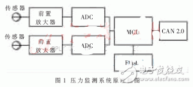
The planetary shifting mechanism of the special vehicle is located in the large box of the integrated transmission, and the surrounding space is narrow and partially immersed in the lubricating oil at a temperature of up to 135 °C. Through demonstration, a small isolation diaphragm pressure sensor was selected and installed on the oil passage of the cylinder accessory. The signal was amplified by a precision instrumentation amplifier and quantified by a high-signal analog-to-digital converter (ADC). The data processing is completed by ATMEL's AVR series microcontroller (MCU) [2], and the processing result is provided to the operator through the CAN2.0 bus to achieve the purpose of protecting the vehicle integrated transmission. The system block diagram is shown in Figure 1.

Since the operating temperature range of the system is relatively wide (-20 °C~135 °C), the temperature variation has the greatest influence on the measurement error of the system. This paper focuses on the research and implementation of the compensation method for measurement error caused by temperature drift [3]. The compensation method of the whole system includes two parts: circuit hard compensation and algorithm soft compensation. The hard compensation includes the process modulation compensation and amplification circuit compensation of the sensor itself; the soft compensation is realized by embedding the B-spline temperature compensation algorithm in the MCU.
1.2 Hard compensation circuit design
The system adopts a silicon piezoresistive pressure sensor, which has the characteristics of small volume, high sensitivity and high resolution, and is widely used. However, temperature drift is the biggest weakness of silicon piezoresistive sensors, including zero temperature drift and sensitivity temperature drift. Since the resistances of the four resistors that make up the bridge cannot be exactly the same, when the input pressure is zero, the bridge output is not zero and has a zero offset. Sensitivity temperature drift is mainly caused by the change of the piezoresistive coefficient of semiconductor materials with temperature. Generally speaking, the sensitivity of piezoresistive sensors decreases with increasing temperature [4].
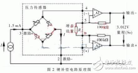
This system uses a small silicon piezoresistive sensor from a US company with a maximum range of 300 psi (1 psi = 6.895 kPa), an output voltage of 0 to 100 mV, and a nonlinearity of ±0.1%. The sensor achieves temperature compensation and zero offset adjustment of the sensor by laser trimming the thick film resistor on the ceramic base. The laser correction resistor provided inside is used to adjust the gain of the external amplifier to ensure the ±0.1% interchangeability range of the sensor. The circuit schematic is shown in Figure 2.

Since the minimum resolution of the sensor is microvolts, it is easy to cause interference during transmission and measurement, resulting in distortion of the result. Therefore, a high-precision, high-common-mode rejection ratio measurement amplification circuit must be used for small signal amplification.
The Fume EXTRA is original 1500 puff salt nicotine disposable vape that comes in a variety of incredible flavors to choose from. This device is great for beginners looking to switch to a vape that doesn`t require any filling or charging. Whether you`re a beginner looking to quit traditional cigarettes or you`re an experienced user wanting maximum puffs, this is the perfect vape to complement your lifestyle. It`s also great for traveling and for those wanting a more discrete vaping experience. Sometimes the original is all you need for everyday puffing.
fume extra vape disposable,fume extra vape kit,fume extra vape strawberry mango,fume extra vape battery,fume extra vape hits
Ningbo Autrends International Trade Co.,Ltd. , https://www.supervapebar.com