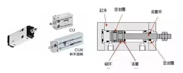
Let's first explain the basic composition and principle of the ordinary cylinder:
Composition of cylinder: cylinder block, piston, sealing ring, magnetic ring (cylinder with sensor)
Principle: Pressurized air moves the piston, and by changing the direction of intake, the direction of movement of the piston rod is changed.
Failure form: the piston is stuck and does not move; the cylinder is weak, the sealing ring is worn, and the air leaks.
The structure and working principle of a typical cylinder
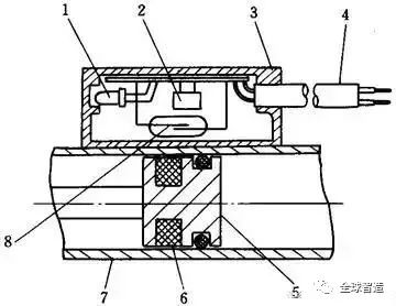
Taking the single-piston rod double-acting cylinder most commonly used in pneumatic systems as an example, the typical structure of the cylinder is shown in the figure below. It consists of cylinder, piston, piston rod, front end cover, rear end cover and seals. The interior of the double-acting cylinder is divided into two chambers by the piston. A cavity with a piston rod is called a rod cavity, and a cavity without a piston rod is called a rodless cavity.
When the compressed air is input from the rodless cavity, the rod cavity is exhausted, and the force formed by the pressure difference between the two cavities of the cylinder acts on the piston to overcome the resistance load and push the piston to move, so that the piston rod extends; When the rodless chamber is vented, retract the piston rod. If the rod cavity and the rodless cavity are alternately inhaled and exhausted, the piston realizes reciprocating linear motion.
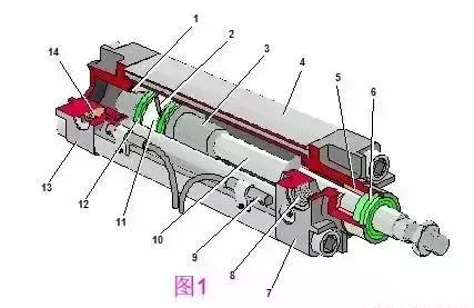
Ordinary double-acting cylinder
1, 3-buffer plunger, 2-piston, 4-cylinder, 5-guide sleeve, 6-dust ring, 7-front end cover, 8-air port, 9-sensor, 10-piston rod, 11-wear-resistant Ring, 12-seal ring, 13-rear end cover, 14-buffer throttle valve
Structure and working principle of mechanical contact rodless cylinder
The structure of the mechanical contact rodless cylinder is shown in Figure 3 below. A groove is opened in the axial direction of the cylinder tube of the cylinder, and the piston and the slider move on the upper part of the groove. In order to prevent leakage and dust-proof needs, the opening part is fixed on the cylinder head at both ends with polyurethane sealing tape and dust-proof stainless steel tape. The piston is connected with the slider, and drives the actuator fixed on the slider to realize reciprocating motion.
The characteristics of this type of cylinder are: 1) Compared with ordinary cylinders, the installation position can be reduced by 1/2 under the same stroke; 2) There is no need to set up an anti-rotation mechanism; 3) It is suitable for cylinder diameters of 10-80mm, and the maximum stroke is ≥ 40mm can reach 7m; 4) High speed, standard type can reach 0.1~0.5m/s; high-speed type can reach 0.3~3.0m/s. The disadvantages are: 1) The sealing performance is poor, and it is easy to produce external leakage. When using a three-position valve, the medium pressure type must be selected; 2) The load force is small, in order to increase the load capacity, a guide mechanism must be added.
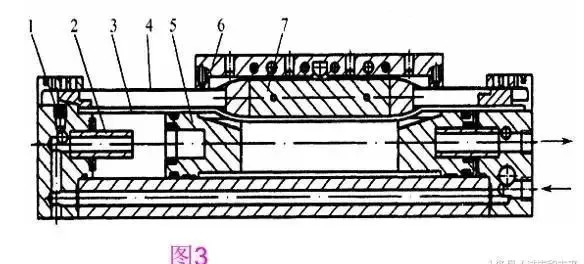
Mechanical Contact Rodless Cylinder
l-throttle valve, 2-buffer plunger, 3-seal band, 4-dust-proof stainless steel band, 5-piston, 6-slider, 7-piston rack
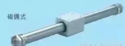
Structure and working principle of magnetic rodless cylinder
The piston drives the moving body outside the cylinder to move synchronously through magnetic force, and its structure is shown in Figure 4. Its working principle is: install a group of high-strength magnetic permanent magnetic rings on the piston, and the magnetic lines of force interact with another group of magnetic rings sleeved outside through the thin-walled cylinder. Because the two groups of magnetic rings have opposite magnetic properties, they have a strong suction force. . When the piston is pushed by the air pressure in the cylinder, under the action of the magnetic force, the magnetic ring sleeve outside the cylinder is driven to move together. The thrust of the cylinder piston must be adapted to the suction of the magnetic ring.
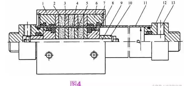
Magnetic Rodless Cylinder
1- Sleeve, 2- Outer magnetic ring, 3- Outer magnetic guide plate, 4- Inner magnetic ring, 5- Inner magnetic guide plate, 6- Gland, 7- Snap ring, 8- Piston, 9- Piston shaft, 10- Buffer plunger, 11-cylinder barrel, 12-end cover, 13-inlet and exhaust ports
Structure and working principle of rack and pinion swing cylinder
The rack-and-pinion swing cylinder is a swing cylinder that rotates the gear through a rack connected to the piston. Its structural principle is shown in Figure 5 below. The piston only performs reciprocating linear motion, with less friction loss and high gear transmission efficiency. The efficiency of this swing cylinder can reach about 95%.
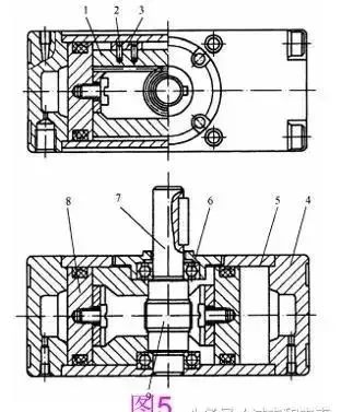
Rack and pinion swing cylinder
1-rack assembly, 2-spring pin, 3-slider, 4-end cover, 5-cylinder, 6-bearing, 7-shaft, 8-piston, 9-gear

Vane swing cylinder and working principle
The structural principle of the single-blade swing cylinder is shown in Figure 6. It is composed of vane shaft rotor (ie output shaft), stator, cylinder and front and rear end covers. The stator and the cylinder are fixed together, and the vanes and the rotor are connected together. There are two air paths on the stator. When the left path is inhaled, the right path is exhausted, and the compressed air pushes the blades to drive the rotor to swing clockwise. Conversely, swing counterclockwise.
The vane-type swing cylinder is small in size and the lightest in weight, but requires high manufacturing precision, is difficult to seal, and has large leakage. Moreover, the contact area of ​​the dynamic seal is large, the frictional resistance loss of the seal is large, and the output efficiency is low, less than 80%. Therefore, it is limited in application, and is generally only used in occasions where the installation position is limited, such as the rotation of fixtures, valve opening and closing, and table indexing.
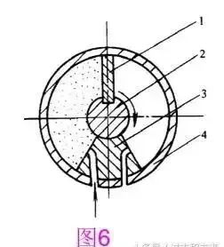
Single vane swing cylinder
1-vane, 2-rotor, 3-stator, 4-cylinder
Principle of Pneumatic Gripper
Pneumatic gripper This actuator is a variant of the cylinder. It can be used to grab objects and realize various actions of the manipulator. In automation systems, pneumatic grippers are often used in handling and conveying workpiece mechanisms to grab, pick and place objects.
Pneumatic gripper has parallel opening and closing fingers (as shown in the figure), toggle swing opening and closing gripper, two-jaw, three-jaw and four-jaw and other types, among which two jaws have flat opening and fulcrum opening and closing drive modes There are linear and rotary.
The opening and closing of the pneumatic gripper is generally driven by the reciprocating linear motion generated by the cylinder piston to drive the crank connecting rod, roller or gear connected to the gripper to drive each gripper to open and close synchronously.
Structure and working principle of film cylinder
The figure below shows the working principle of the diaphragm cylinder. There are two kinds of diaphragms: flat diaphragm and disc-shaped diaphragm. Generally, they are made of interlayer rubber, steel sheet or phosphor bronze sheet, and the thickness is 5-6mm (1-2mm thick diaphragm is useful).
The function of the diaphragm cylinder shown in the figure below is similar to that of a spring-returned piston-type single-acting cylinder. During operation, the diaphragm pushes the piston rod to move under the action of compressed air. Its advantages are: simple structure, compactness, small size, light weight, good sealing, not easy to leak, simple processing, low cost, no wearing parts, convenient maintenance, etc. It is suitable for occasions with short strokes. The disadvantage is that the stroke is short, generally not more than 50mm. Flat diaphragms have a shorter stroke, about 1/10 of their diameter.
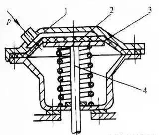
Film cylinder
1-cylinder, 2-diaphragm, 3-diaphragm, 4-piston rod
Structure and working principle of combined cylinder with valve
The valve cylinder is a combined pneumatic actuator composed of a cylinder, a reversing valve and a speed control valve. As shown in the figure below, it eliminates the need for connecting pipes and pipe joints, reduces energy loss, and has the advantages of compact structure and convenient installation. The valve with valve cylinder has various control methods such as electric control, pneumatic control, machine control and manual control. There are several installation forms of the valve, such as the tail and the upper part of the cylinder. As shown in the figure below, the electromagnetic reversing valve is installed on the upper part of the cylinder. When there is an electrical signal, the electromagnetic valve is switched, and the output air pressure can directly control the action of the cylinder
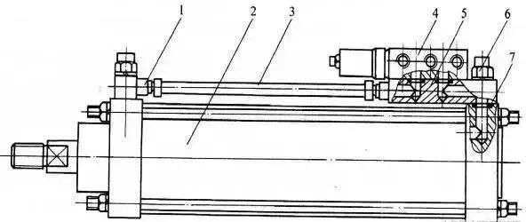
Combined cylinder with valve
1-pipe joint, 2-air cylinder, 3-air pipe, 4-electromagnetic reversing valve, 5-reversing valve base plate, 6-one-way throttle valve assembly, 7-sealing ring.
The structure and working principle of the magnetic switch cylinder
Magnetic switch cylinder means that a magnetic ring is installed on the piston of the cylinder, and a magnetic switch is directly installed on the cylinder barrel. The magnetic switch is used to detect the position of the cylinder stroke and control the reciprocating motion of the cylinder. Therefore, it is not necessary to install a stroke valve or a stroke switch on the cylinder barrel to detect the position of the cylinder piston, nor to set a stopper on the piston rod.
Its working principle is shown in the figure below. It is to install a permanent magnetic ring on the cylinder piston and a reed switch on the cylinder shell. The switch is equipped with reeds, protection circuits and action indicators, etc., all of which are encapsulated in a box with resin. When the piston equipped with the permanent magnet moves to the vicinity of the reed, the magnetic field line is magnetized by the reed, and the two reeds are attracted and contacted, and the switch is turned on. When the permanent magnet returns and leaves, the magnetic field weakens, the two reeds spring open, and the switch is turned off. As the switch is turned on or off, the solenoid valve is reversed, thereby realizing the reciprocating motion of the cylinder.
Magnetic switch cylinder
1- Action indicator light, 2- Protection circuit, 3- Switch shell, 4- Conductor, 5- Piston, 6- Magnetic ring, 7- Cylinder barrel, 8- Reed switch
Anti-reflection coating, also known as anti-reflection coating, its main function is to reduce or eliminate the reflected light of optical surfaces such as lenses, prisms, and plane mirrors, thereby increasing the amount of light transmitted by these components, reducing or eliminating stray light in the system, and anti-reflection coating It is an optical coating with a wide range of applications, widely used in daily life, industry, astronomy, military science, electronics and other fields.
Reflective film generally reads metal and medium, and both have a large extinction coefficient. When the light beam enters the metal surface from the air, the amplitude of the light entering the metal is rapidly attenuated, so that the light energy entering the metal is correspondingly reduced, and the reflection Light energy increases. The greater the extinction coefficient, the faster the light amplitude decays, the less light energy enters the metal, and the higher the reflectivity.
The function of the spectroscopic film is to generate multiple paths of light as several directional collimators to calibrate the optical path and improve the measurement accuracy. Considering the different spectral response curves of the light source and the receiving device diode array, the incident light in the optical path needs to pass through multiple spectroscopic film surfaces.
Filter film refers to a film layer that attenuates light intensity or changes the spectral composition. The main purpose is to reduce or increase the color temperature, change the wavelength, block unwanted light, change the color, etc.
Anti-Reflection Coating,Product Reflective Coating,Product Beam Splitter Coating,Product Filter Coatign Products
Bohr Optics Co.,Ltd , https://www.bohr-optics.com