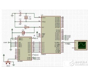
There are a total of 8 timers in the STM32F103ZET6, of which the advanced timers are TIM1-TIM5, TIM8, a total of 6.
The timer I output PWM here is TIM2, and the idle timer is TIM3. Take TIM2 as the master timer, and TIM3 as the slave timer to count the number of output pulses of TIM2.
It can be seen from the table that TIM3 selects TIM2 as the trigger source from the timer, and needs to configure TS=001, that is, select ITR1.
To achieve the function of controlling the number of output PWMs through the timer, there is one configuration method as follows:

void TIM2_Master__TIM3_Slave_Configuration(u32 PulseFrequency)
{
TIM_TimeBaseInitTypeDef TIM_TimeBaseStructure;
TIM_OCInitTypeDef TIM_OCInitStructure;
u16 nPDTemp ;
/* ------------------------------------------------ -----------------------
TIMx Configuration: generate 4 PWM signals with 4 different duty cycles:
TIMxCLK = 72 MHz, Prescaler = 0x0, TIMx counter clock = 72 MHz
TIMx ARR Register = 0 => TIMx Frequency = TIMx counter clock/(ARR + 1)
TIMx Frequency = 72MHz.
-------------------------------------------------- --------------------- */
TIM_Cmd(TIM2, DISABLE);
nPDTemp = 72000000UL/PulseFrequency;
// Time base configuration: configure PWM output timer - TIM2
/* Time base configuration */
TIM_TimeBaseStructure.TIM_Period = nPDTemp-1;
TIM_TimeBaseStructure.TIM_Prescaler = 0;
TIM_TimeBaseStructure.TIM_ClockDivision = 0;
TIM_TimeBaseStructure.TIM_CounterMode = TIM_CounterMode_Up;
TIM_TimeBaseStructure.TIM_RepetitionCounter = 0;
TIM_TimeBaseInit(TIM2, &TIM_TimeBaseStructure);
// Output configuration: configure the PWM output timer - TIM2
/* PWM1 Mode configuration: Channel1 */
TIM_OCInitStructure.TIM_OCMode = TIM_OCMode_PWM1;
TIM_OCInitStructure.TIM_OCPolarity = TIM_OCPolarity_High;
TIM_OCInitStructure.TIM_OutputState = TIM_OutputState_Enable;
TIM_OCInitStructure.TIM_Pulse = nPDTemp""1;//50%
TIM_OC1Init(TIM2, &TIM_OCInitStructure);
TIM_OC1PreloadConfig(TIM2, TIM_OCPreload_Enable);
// Time base configuration: configure the pulse count register - TIM3
TIM_TimeBaseStructure.TIM_Period = 0xFFFF;
TIM_TimeBaseStructure.TIM_Prescaler = 1;
TIM_TimeBaseStructure.TIM_ClockDivision = 0;
TIM_TimeBaseStructure.TIM_CounterMode = TIM_CounterMode_Up;
TIM_TimeBaseStructure.TIM_RepetitionCounter = 0;
TIM_TimeBaseInit(TIM3, &TIM_TimeBaseStructure);
/* Output Compare Active Mode configuration: Channel1 */
TIM_OCInitStructure.TIM_OCMode = TIM_OCMode_Inactive;
TIM_OCInitStructure.TIM_OCPolarity = TIM_OCPolarity_High;
TIM_OCInitStructure.TIM_OutputState = TIM_OutputState_Enable;
TIM_OCInitStructure.TIM_Pulse = 0xFFFF; // The configuration value here has little meaning
TIM_OC1Init(TIM3, &TIM_OCInitStructure);
// Configure TIM2 as the master timer
/* Select the Master Slave Mode */
TIM_SelectMasterSlaveMode(TIM2, TIM_MasterSlaveMode_Enable);
/* Master Mode selection */
TIM_SelectOutputTrigger(TIM2, TIM_TRGOSource_Update);
// Configure TIM3 as slave timer
/* Slave Mode selection: TIM3 */
TIM_SelectSlaveMode(TIM3, TIM_SlaveMode_Gated);
TIM_SelectInputTrigger(TIM3, TIM_TS_ITR1);
TIM_ITConfig(TIM3, TIM_IT_CC1, ENABLE);
TIM_Cmd(TIM2, DISABLE);
TIM_Cmd(TIM3, DISABLE);
}
The interrupt service routine is as follows:
u8 TIM2_Pulse_TIM3_Counter_OK = 0;
void TIM3_IRQHandler(void)
{
if (TIM_GetITStatus(TIM3, TIM_IT_CC1) != RESET)
{
TIM_ClearITPendingBit(TIM3, TIM_IT_CC1); //Clear the interrupt flag bit
TIM_Cmd(TIM2, DISABLE); // Turn off the timer
TIM_Cmd(TIM3, DISABLE); // Turn off the timer
TIM2_Pulse_TIM3_Counter_OK = 1;
}
}
The application is:
u16 pulsecnt = 10000;
void main(void)
{
SystemSetup(); // Initialize the kernel and peripherals
TIM2_Master__TIM3_Slave_Configuration(10000);//Configure the pulse output of TIM2 to 10k
while(1)
{
TIM_ITConfig(TIM3, TIM_IT_CC1, DISABLE); /* TIM enable counter */
TIM_Cmd(TIM3, ENABLE);
TIM3->CCR1 = pulsecnt;
TIM3->CNT = 0;
TIM_ITConfig(TIM3, TIM_IT_CC1, ENABLE);
TIM_Cmd(TIM2, ENABLE); /* TIM enable counter */
while(TIM2_Pulse_TIM3_Counter_OK == 0);
}
}
In this configuration, the comparison interrupt of TIM3 is used. I have not tried other methods, but I think it should be possible, such as using a timer to update the interrupt.
L Series Lead Acid Battery,Custom Valve Regulated Battery,12V 38Ah Battery,12V 65Ah Lead Acid Battery
Wolong Electric Group Zhejiang Dengta Power Source Co.,Ltd , https://www.wldtbattery.com