1. Remotely control the supply and de-energization of home appliances.
2. Remotely control the power supply of the electrical appliances and delay the automatic shut-down.
3. Change the password remotely or locally, simulate the ringing times of the off-hook, and set all the remote control settings.
4. Two-way contact output (connecting 220V power socket), one DC output (12V), one level output (including two output terminals: positive and negative, which can be directly connected to the control terminal of the relevant electrical appliance).
5. It has a second function setting and adds a remote monitor function.
6. The remote operation has a status tone.
7. After all set working states are powered off, the data is saved (100 years) without loss.
Second, the circuit worksTelephone remote control monitor circuit diagram as shown in the figure.
IC3A, DW1, R7 make up the phone line pick up detection and circuit ring signal detection circuit.Usually the telephone line voltage makes DW1 breakdown, the output current of the optocoupler is relatively small, ensure the output end output low level signal, P3.0 is pulled down At low level, the main task of the microcontroller is to monitor the voltage change of P3.0.
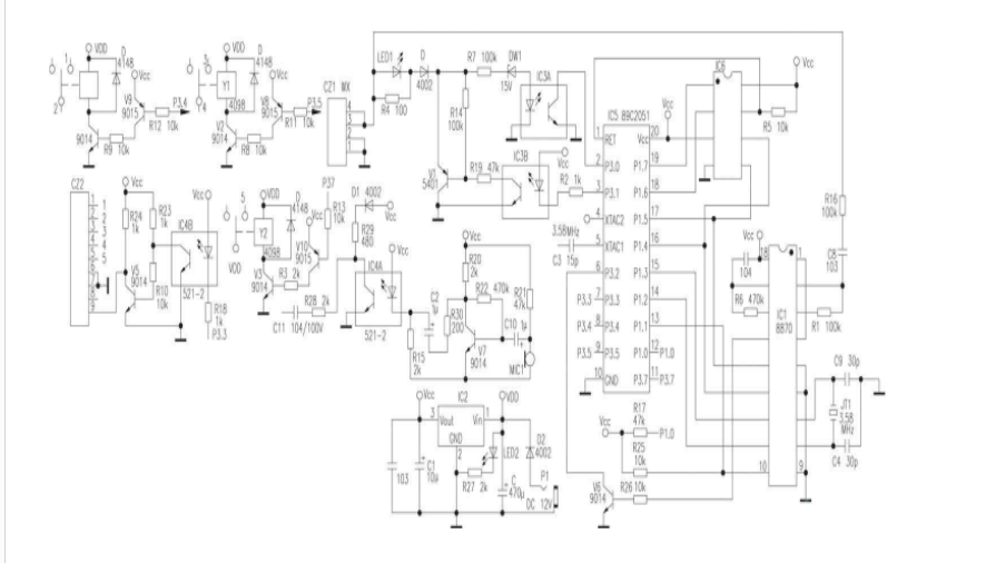
When the telephone set connected in parallel with the telephone remote controller picks up the telephone or the telephone remote control listener receives the ring signal and reaches the specified ringing frequency, the telephone remote controller simulates the off-hook and the voltage on the telephone line is reduced from 48V to 7~ 8V At this time, DW1 is cut off, and P3.0 is pulled up by the internal pull-up resistor. After the microcontroller detects that P3.0 is high, external interrupt 0 is turned on and P3.2 receives the signal from IC1 (8870). The strobe signal, once the strobe signal arrives, receives the data of the double-voice signal on the 8870 data terminal.
If a ring signal appears on the telephone line, a ringing voltage of 90Vp-p causes the IC3A output to turn on and off at the ringing frequency, P3.0 automatically detects the ring signal from the detection of IC3A output high signal. Still on the off-hook signal, for a true 25-Hz square-wave ringing signal, the MCU counts the number of rings after each ringing signal is completed, and compares the data in the ring-count counter with the set ring-off pick-up data. The two are equal, P3.1 is set to low level, and the analog pick-up is realized through driving the triode V1 of IC3B.After the analog pick-up, the calling party can hear three ringing sounds from P3.1 in the remote monitor. The caller enters the password, and the telephone remote control listener verifies the password, the password correctly transmits the sound of the verification passed, the password is incorrect and the failed prompt sound is given, and the calling user is allowed to input the password again.The password entered the second time is correct. Enter the following program, the password entered twice is not correct, the telephone remote control hangs up.After the correct input of the password by the caller, you can enter different numbers to perform remote control through the keys of the remote telephone. Make different control tasks.
IC1 receives the double audio signal on the telephone line, and converts it into the data to the one-chip computer.The IC1 clock signal adopts 3.579545MHz crystal, the clock signal of the one-chip computer is also taken from the oscillation output end of IC1.
The IC6 X25045 is an EEPROM circuit that includes a watchdog and a voltage monitor.This circuit is used with the 89C2051 to solve the problem of setting data retention after a power failure, and to solve the problem of setting data reset and low-voltage detection and protection data for runaway. The problem is that the I/O ports associated with the microcontroller and external circuits are optically isolated, which greatly improves the anti-interference ability of the microcontroller and ensures the reliable operation of the circuit.
The enablement of IC6 and IC1 is controlled by the single-chip microcomputer. In normal operation, IC1 and IC6 do not work at the same time, so the data lines of the two circuits can share the I/O port.
The P3.4, P3.5, and P3.7 of the single-chip microcomputer each control a relay circuit to realize the power supply control of the household appliances, and the two-transistor is isolated and amplified between the control output pins of the single-chip microcomputer and the relay, and the front-stage triode is used to invert. Phase and post-triodes push the relays to work, and the way each relay works, that is, the remote control of the telephone, is determined by the user's operation and function settings.
The first relay can be turned on or off by remotely pressing different keys. It can also be turned on by remote operation (power supply), and then input 3 digits. It is set to delay after 001~999 minutes.
In addition to the second relay, which can be turned on or off by remote control of different buttons, there is a second function setting.After the second function is set, the working status is determined by the working status of the telephone line. Under normal circumstances, the second output is off. When the telephone line is lowered due to the off-hook voltage, the relay delays for 1 second to pull in and output the power supply state; when the telephone line is detected to hang up (the line voltage recovers 48V), the power supply is automatically stopped after 3 seconds delay. The function is generally used for automatic power supply of communication equipment, for example, a telephone line and a facsimile machine are connected to a telephone line, and the telephone is mainly used, and a facsimile machine is also commonly used, and when a facsimile machine is required, it can receive or send a facsimile in time. At this point, using a second way to control a socket, as the power supply of the fax machine, fax machine usually does not provide power, fax, fax machine off the hook, the phone line voltage is reduced, the fax machine is automatically powered, the fax operation is the same as the original. When a call comes in, the phone rings, the called party picks up the phone, and the fax machine powers up. When the other party requests a fax, press the Fax Start button to receive the fax. In this way, it is not only convenient to receive and send faxes, but also to ensure normal telephone line calls, and by setting the number of rings that the telephone remote control listener simulates to pick up, it also ensures remote control of other electrical equipment remotely.
The third relay is a monostable output, remote single-key control, after pressing the operation button, the relay pulls in, outputs 12V DC, and delays automatically resets for 1.5 seconds.The third channel is mainly used to control the opening and closing of electronic locks, such as Control of the garage electronic lock.
The fourth level is the level output, and there are two output terminals in positive and negative directions, which are used to control some home appliances with direct level control.
V7 and peripheral components form an amplifying circuit, and the working state is controlled by the single-chip microcomputer, usually P1.0 is high level, the amplifying circuit can not establish a normal working point, there is no amplification capability, and the surrounding environment sound is not transmitted to the telephone line. When 0 is pulled down to a low level, the amplifier circuit enters a normal amplification state, and the MIC1 receives the surrounding sound and converts it into an electrical signal and sends it to V7 through C10. The resistance of the resistor R15 is selected to make the IC4A work in a linear state. The audio signal output from V7 is coupled to the input of IC4A via R30 and C2, and the output audio signal is directly added to the base of V1. The operating point of V1 is adjusted in the amplified state by R19. The above audio signal is amplified by the V1 emitter and output. Send the call line to the calling party, caller's monitoring time is 1 minute, divided into listening to 20 seconds, stopping for 5 seconds, listening for 20 seconds, stopping for 5 seconds, and finally listening for 10 seconds to end and hang up. Within seconds, you can also unlock the monitor via the telephone button or continue to control the above 4-way working status. In the non-monitoring state, if there is no key operation within 20 seconds, the remote control Hearing automatically hang up.
The contact output of the three relays in the circuit and the level output of the fourth circuit are all output by a terminal block, and the control line can be directly and reliably connected to the terminal. The AC output is a contact (switch), when the connection is not connected. The output is not live and it is safe and reliable to use.
Application-Specific Integrated Circuit refers to an integrated circuit specifically designed to perform a specific computing task. It is very common to use ASIC for mining in the field of blockchain. This article will analyze the principle of ASIC mining and why it should be anti-ASIC.
For Bitcoin, mining has gone through four stages: CPU, GPU, FPGA and ASIC. GPU is naturally suitable for parallel simple operations, so the execution of SHA256 is much higher than the CPU. FPGA is a programmable hardware, because it has a certain degree of universality, so the unit price will be relatively expensive. ASIC has a large initial design investment, but the unit price will be cheaper after mass production. Therefore, if you can determine that the market size is relatively large, the use of ASIC technology will be the most cost-effective.
This is the basic principle of ASIC.
In a nutshell, mining is running complicated calculations in the search for a specific number. Whether it`s an ASIC miner or a GPU mining rig, mining hardware must run through many calculations before finding that number. In proof of work systems like Bitcoin, the first one to find that number gets a reward - at the time of writing, 12.5 Bitcoins worth around $96,850. That reward will fall to 6.25 Bitcoins in May 2020.
There are so many people and powerful computing systems trying to mine Bitcoin that miner groups form to find that number and share the profit. Even more, the faster your hardware, the more you earn. That`s why people who can afford it opt for ASIC miners because it gives them the greatest chance of earning cryptocurrency in exchange for their investment.
Each cryptocurrency has its own cryptographic hash algorithm, and ASIC miners are designed to mine using that specific algorithm. Bitcoin ASIC miners are actually designed to calculate the SHA-256 hash algorithm. In the case of Litecoin, it uses Scrypt. That means technically they could mine any other coin that`s based on the same algorithm, though typically, people who buy ASIC hardware designed for Bitcoin mine that specific digital currency.
Antin S19J Pro 96Th,Antin S19J Pro,S19J Pro 96T Antminer,s19j pro antminer,s19 xp antminer
Shenzhen YLHM Technology Co., Ltd. , https://www.sggminer.com