Ankerui Cui Tingyu
Jiangsu Ankerui Electric Manufacturing Co., Ltd.
Abstract: Introduce the Shanghai Guangdian Intelligent Internet of Things·Archive Data Processing Pilot Test Base, which uses comprehensive protection devices, multi-function meters, transformer temperature controllers, and DC screens to collect various electrical parameters and status signals at the distribution site. The system adopts the method of on-site networking. After networking, it communicates via fieldbus and transmits it to the background. The Acrel-2000 power monitoring system realizes real-time monitoring and management of the power consumption of the substation's power distribution loop.
Keywords: Shanghai Guangdian Intelligent Internet of Things·File Data Processing Pilot Test Base; 10KV Substation and Distribution Station; Comprehensive Protection Device; Acrel-2000; Power Monitoring System.
0 Overview
Shanghai Guangdian Intelligent Internet of Things·Archive Data Processing Pilot Base is located at Xianghuaqiao Street, Qingpu Export Processing Zone, Qingpu District, Shanghai. The base is located on the south side of the current Songze Avenue and the west side of the future Songbo Road. The main purpose is industrial plants and related supporting buildings. The total area of ​​the project is approximately 30,180 square meters and the total construction area is approximately 84,882 square meters.
This project undertook the construction of its substation power monitoring system. The substation has a total of 2 10KV incoming lines, and the entire project is powered by 2 1600KVA transformers and 2 2000KVA transformers. The integrated protection device in the substation, Multifunctional instruments, transformer temperature controllers, DC screens and other equipment use RS485 bus networking to connect to the data collector in the substation, and transmit the data to the back office of the duty room through the super five lines.

1 Demand analysis
The power monitoring system needs to realize data centralized management, analysis and processing. The software function requirements are as follows:
Monitoring information such as voltage, current, power, power factor, power consumption, switching value, etc. is refreshed in real time, and displayed intuitively and dynamically in the form of a graph. The sub-screen of each circuit displays the electrical parameters, circuit name and other information of the circuit.
Draw a trend curve for the current of each loop to facilitate analysis of the power distribution operating conditions of the loop.
The function of collectively reading the electric energy of each circuit, and can generate electricity consumption reports that meet the customer's management requirements within a time period.
Real-time communication status display for each loop instrument.
Multi-user authority management, convenient for hierarchical operation.
This technical condition applies to the power distribution room of the Shanghai Guangdian Intelligent Internet of Things·Archive Data Processing Pilot Base. The supplier’s products should have high safety and reliability, easy to expand, easy to repair and maintain. The products provided by the supplier shall at least meet the technical conditions, but not limited to this, and their technical performance shall meet the requirements for data monitoring in the power distribution room.
2 Technical standards
The countries and industries cited in this technical specification are marked as follows:
ISO/IEC11801 "International Integrated Wiring Standard"
GB/50198 "Technical Specification for Monitoring System Engineering"
GB50054-2011 "Code for Low Voltage Power Distribution Design"
IEC 61587 "Electronic Equipment Mechanical Structure Series"
DL/T448-2000 "Technical Management Regulations for Electric Energy Metering Devices"
DL/T 698.1-2009 "Part 1: General Provisions"
DL/T 698.2-2010 "Part 2: Technical Specifications of the Master Station"
DL/T 698.31-2010 "Part 3.1: Technical Specifications for Electric Energy Information Collection Terminals-General Requirements"
DL/T 698.35-2010 "Part 3-5: Technical Specifications for Electric Energy Information Collection Terminals-Special Requirements for Low-Voltage Centralized Meter Reading Terminals"
DL/T 698.41-2010 "Part 4-1: Communication Protocol-Communication between the Master Station and the Electric Energy Information Collection Terminal"
DL/T 698.42-2010 "Part 4-2: Communication Protocol-Concentrator Downlink Communication Protocol"
DL/T 698.41-2010 "Part 4-1: Communication Protocol-Communication between the Master Station and the Electric Energy Information Collection Terminal"
DL/T 698.42-2010 "Part 4-2: Communication Protocol-Concentrator Downlink Communication Protocol"
3 System solution
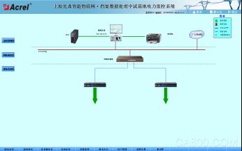
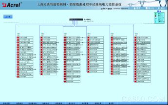
The monitoring system mainly realizes the monitoring and management of the electricity safety of the power transformation and distribution of the Shanghai Guangdian Intelligent Internet of Things·Archive Data Processing Pilot Base. The monitoring scope includes 8 comprehensive protection devices, 4 transformer temperature controllers, 214 multifunctional meters, and 1 DC screen. Comprehensive protection devices, transformer temperature controllers, multi-function meters, and DC screens are connected to the data collector in the substation through the 485 bus, and then the data is uploaded to the substation duty room host through the optical fiber and network cable, so as to realize the bus on the monitoring host Data connection between the upper instrument and the monitoring host. As shown in the figure below: station control management layer, network communication layer and field device layer.
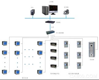
System network topology diagram
1) Station control management
The station control management layer is the direct window of human-computer interaction for the management personnel of the power monitoring system. Mainly refers to the industrial computer, monitor, UPS, etc. placed in the duty room.
2) Network communication layer
The communication layer is mainly composed of collectors and bus networks. The main function of the collector is to monitor on-site intelligent instruments, comprehensive protection devices, transformer temperature controllers, and DC screens; the main function of the bus network is to realize data interaction, so that the management of the distribution system is centralized, informatized, and intelligent, which greatly improves The safety, reliability and stability of the power distribution system have truly achieved the goal of unattended operation.
3) Field equipment layer
The field equipment layer is the data acquisition terminal, which is mainly composed of transformer temperature controller, comprehensive protection device, multi-function instrument, and DC screen. It is connected to the communication server through the shielded twisted pair RS485 interface and the MODBUS communication protocol bus connection. Reach the monitoring host of the power distribution room for networking and realize remote monitoring.
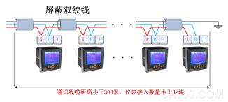
Smart instrument connection diagram
Field instruments are connected hand in hand via shielded twisted pair (RVVSP2*1.0). Each bus is connected to about 25 smart instruments, and then upload the data to the serial server, and then upload the data to the local monitoring terminal. The specific connection diagram is as follows:
4 System function
Features
The system adopts a full Chinese interface, which is simple and convenient to operate; stable and reliable operation; the system has a system diagram display, a simulation diagram display and a network structure diagram display; the system provides a friendly human-computer interaction interface, and all operations can be performed on the interface. And has a remote display function.
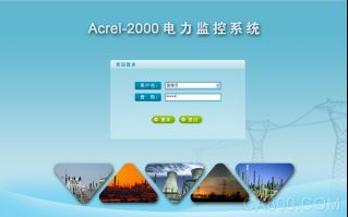
login interface
In order to ensure the safe and stable operation of the system, the Acrel-2000 power monitoring system is equipped with user authority management functions. Through user authority management, unauthorized operations (such as modification of the name of the power distribution circuit, etc.) can be prevented. The login name, password and operation authority of users of different levels can be defined to provide reliable security guarantee for system operation, maintenance and management.
Main function: The user's level is divided into four levels: operator, monitor, engineer, and system administrator. Each level can be assigned different operation permissions, including entering operation, exiting operation, remote operation, report management, system configuration, User management, etc. The system administrator is the highest level user, and the higher level users can add or delete the next level users.
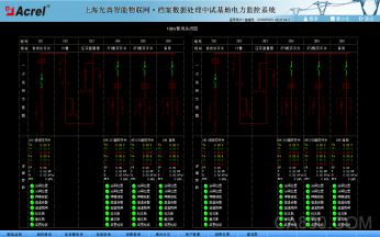
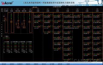
Power distribution monitoring interface
Acrel-2000 power monitoring system has a friendly human-machine interface, which can visually display the operating status of distribution lines in the form of a distribution diagram, and monitor the voltage, current, power, power factor, energy and other electrical parameters of each circuit in real time. Dynamically monitor the closing and opening status of circuit breakers, isolating switches, ground cutters, etc., and related faults, alarms and other signals.
Main functions: A diagram shows the name of each circuit, current, voltage, total active power, total power factor, closing and opening states of circuit breakers, ground cutters, isolating switches, spring energy storage state, and handcart position state.
Power distribution monitoring function
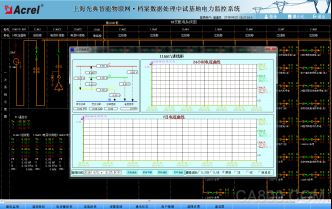
Detailed electrical parameter query
In the power distribution diagram, click with the mouse to view the detailed electrical parameters of the circuit, including three-phase current, three-phase voltage, three-phase total active power, total reactive power, total power factor, positive active energy, and you can view them 24-hour phase current trend curve and 7-day phase current trend curve.
Distribution circuit details

DC screen details
Communication status
Acrel-2000 power monitoring system supports real-time monitoring of the communication status of each device connected to the system, and can completely display the network structure of the entire system; it can diagnose the communication status of the device online, and automatically display the faulty device on the interface when a network abnormality occurs Or components and faulty parts. It is convenient for operation and maintenance personnel to grasp the communication status of each equipment on site in real time, maintain abnormal equipment in time, and ensure the stable operation of the system.
Main function: It has a complete system communication topology diagram, real-time display of equipment communication status, red status indicates normal communication of the corresponding equipment, and green status indicates abnormal communication of the equipment. Beside the system host and serial server/communication management machine, the assigned IP address of the device is marked, and the device address and device loop number are marked next to each device.
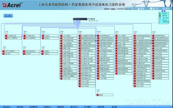
Communication status diagram
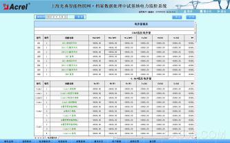
Electric parameter report
Acrel-2000 power monitoring system has storage and management functions of real-time power parameters and historical power parameters. All real-time collected data and sequential event records can be saved to the database. The parameters that need to be queried can be customized in the query interface , Specify the time or select to query the most recently updated record data, etc., and display it in the form of a report.
Main function: Query the operating parameters of each circuit or equipment at a specified time. The electrical parameter information displayed in the report should include: each phase current, three-phase voltage, total power factor, total active power, total reactive power, forward active energy, etc. The electrical parameter report also supports the export of Excel format files, and can also export PDF format files according to user requirements.
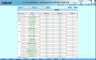
Energy report
Acrel-2000 power monitoring system supports the integrity of the system with a rich report body. The system has the function of regular meter reading and summary statistics. Users can freely query the power consumption of each distribution node in any period of time since the normal operation of the system, that is, the statistical analysis report of the power consumption of the node's incoming line and the power consumption of each branch circuit. This function makes the electricity consumption visible and transparent, and can be analyzed and traced when the electricity consumption error is too large to maintain the correctness of the measurement system.
Main function: Time selection box with start time and end time. After selecting the time period you want to query, click the query button to query the power consumption of all power distribution circuits within the system project range. The report can be exported and saved in Excel format via the export button, and the report can be printed via the print button.
Energy report function
Current limit setting
The current limit setting is designed for each loop of the power distribution system. It is convenient for the power distribution maintenance personnel to change the power current setting limit according to the on-site power demand in time. When the current exceeds the limit, the loop power is controlled in time to ensure the reliability of power supply and provide protection for the energy rights of users.
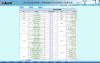
Current limit setting
Alarms and events
Real-time alarm
The real-time alarm window monitors the remote measurement collected by the system. The alarm window will automatically open when the system is running, and it will always be hidden in the background.
When the current or voltage exceeds the limit and the alarm limit is touched, the "Corresponding Real-time Alarm" window will automatically pop up and display the specific alarm information in red font: circuit name, over-limit electrical parameters, alarm value, etc.
Historical alarm
By adjusting the start time and end time, you can query the system alarm information in any time period in the past, including telemetry alarm and remote signal alarm, as well as specific alarm time, alarm type, alarm content, etc.
5 Conclusion
In the application of today’s power distribution facilities, the power distribution safety of substations is very important. The Acrel-2000 power monitoring system introduced in this article can be applied to the Shanghai Guangdian Intelligent Internet of Things·Archive Data Processing Pilot Test Base. The real-time monitoring of the power consumption of the power supply and distribution circuit of the substation can not only display the power consumption of the circuit, but also has the network communication function, which can form a power monitoring system with serial server, computer, etc. The system realizes the analysis and processing of the collected data, real-time display of the operation status of the distribution circuits in the substation, and has pop-up alarm dialog boxes, voice prompts, SMS alarm lights for opening and closing, load limit violations, and generates various energy reports , Analysis of curves, graphs, etc., convenient for remote meter reading, analysis and research of electric energy. The system is safe, reliable and stable in operation, providing a true and reliable basis for solving electricity problems.
references:
[1]. Ren Zhicheng Zhouzhong. Principle and Application Guide of Digital Instruments for Electric Power Measurement[M]. Beijing. China Electric Power Press. 2007. 4
[2]. Edited by Zhou Zhongzhong. Smart grid user-side power monitoring and power management system product selection and solutions [M]. Beijing. Mechanical Industry Press. 2011.10
About the author: Cui Tingyu, male, undergraduate, Jiangsu Ankerui Electric Manufacturing Co., Ltd., whose main research direction is power supply and distribution monitoring system for intelligent buildings. Email: el.cn QQ: 2881068608 Mobile: 18860995251 Tel: 0510-86179851 Fax: 0510-86179975 Website: http://
Guangdong Ojun Technology Co., Ltd. , https://www.ojunconnector.com