Abstract: Due to its excellent physical characteristics, SiC power MOSFETs are increasingly being valued in high-frequency applications such as charging piles and solar inverters. Because the switching frequency of the SiC MOSFET is as high as several hundred KHz, the design of the gate drive becomes extremely critical in the application. Because the high short-circuit current of the SiC MOSFET generates extremely high heat during the short-circuit process, the SiC MOSFET needs fast short-circuit detection and protection. At the same time, the current turn-off rate also needs to be controlled within a certain range to prevent excessive voltage spikes during turn-off. This article discusses several methods that can achieve fast short-circuit protection, and has verified the feasibility through actual tests.
SiC MOSFET short circuit characteristics
Power devices have many different short-circuit modes. The most serious one is bridge short-circuit. In this short-circuit mode, the current rises rapidly and the device is subjected to bus voltage. We need to study the behavior of the MOSFET in this short-circuit mode first.
The short-circuit test platform is shown in Figure 1. The test driver board was developed by Infineon specifically for single-tube SiC MOSFETs. The device under test is IMZ120R045M1 in TO-247 4pin package. The test is performed at room temperature.
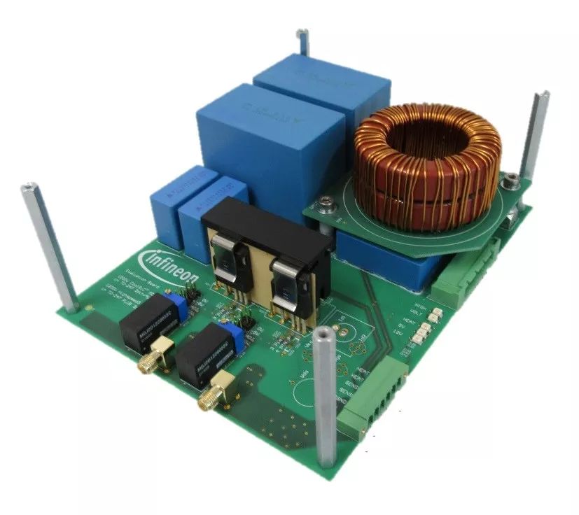
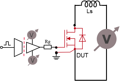
Figure 1 SiC power MOSFET short-circuit characteristic test platform and test circuit
Figure 2 shows the short-circuit current waveforms under the two bus voltages of 400V and 800V, and the gate voltage is 12V, 15V, and 18V. In the initial stage of the short circuit, the drain current rises rapidly and reaches the highest value. When the gate voltage is 12V and 15V, the current peaks are 170A and 270A, respectively. After the current peak, the drain current begins to drop significantly, and the gate voltage is 130A and 180A when the gate voltage is 12V and 15V, respectively. This is because the carrier mobility decreases with the increase in temperature, so that the short-circuit current decreases. The test waveform confirmed that the TO-247 packaged 4pin CoolSiCâ„¢ MOSFET has a short-circuit capability of at least 3us under the condition of 15V gate drive voltage. After the short-circuit pulse ends, two situations may occur: 1) The device under test is safely shut down and the drain current drops to 0A. 2) The energy accumulated during the short circuit exceeds the device limit. For example, if the gate drive voltage is too high or the bus voltage is too high, it may cause thermal runaway and cause device failure, as shown by the green line in Figure 2(b). This curve shows that the bus voltage is 800V and the gate voltage is 18V. When the short-circuit pulse is extended to 4us, the device fails.
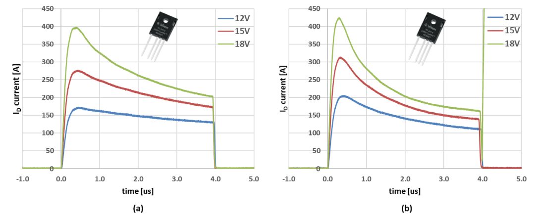
Figure 2 Short-circuit current waveforms of IMZ120R045M1 under different gate voltages (a) Vdc=400V (b) Vdc=800V
From Figure 2, we can see that the short-circuit current is positively correlated with the gate voltage, and higher gate voltage leads to higher short-circuit current, which in turn causes higher junction temperature and lower carrier mobility. Therefore, the drop in Id under high gate voltage will be greater.
Figure 3 shows the short-circuit current of IMZ120R045M1 at 15V gate voltage and 400V and 800V bus voltage. It can be seen that the bus voltage has little effect on the peak current. When the chip starts to be heated, the 800V bus voltage will generate more energy, causing the junction temperature of the chip to be higher than the 400V bus voltage. Therefore, when VDC=800, the drain current drops faster, and the peak value is soon lower than 400V VDC. .
Figure 3 Short-circuit current of IMZ120R045M1 under different bus voltages
SiC MOSFET short circuit protection method
There are currently 4 commonly used short-circuit detection and protection methods, the schematic diagram of which is shown in Figure 4. The most direct way is to use a current probe or shunt resistor to detect the drain current. The most commonly used method in the industry is to detect the saturation pressure drop. When the MOSFET is normally on, the drain voltage is about 1~2V. When a short circuit occurs, the short circuit current will quickly rise to the saturation value, and the drain voltage will also rise to the bus voltage. Once the tested Vds is higher than the preset reference value, the device under test will be considered to enter a short-circuit state.
Another typical short-circuit detection solution is to monitor di/dt. In high-power IGBT modules, there is a parasitic inductance between the Kelvin emitter and the power emitter. In the switching operation, the changing current will generate a voltage VeE across the inductor. By detecting this voltage, it can be judged whether the device enters a short-circuit state.
In the on state, Vds detection requires a certain blanking time to prevent false triggering. In addition, the detection method based on di/dt depends on the value of the parasitic inductance LeE. In addition, short-circuit detection can also be achieved by detecting the characteristics of the gate charge. When a short circuit occurs, the gate waveform is different from the normal switching waveform, and there is no Miller platform. This method does not require blanking time and does not rely on LeE.
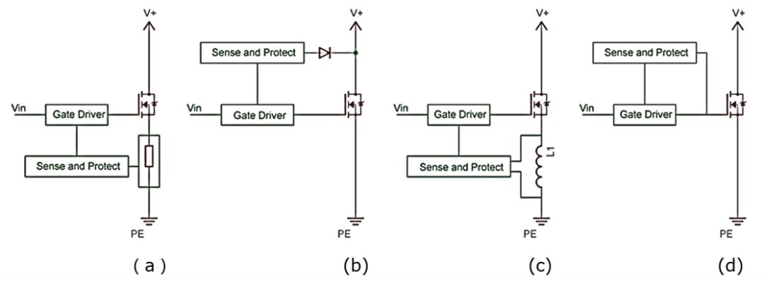
Figure 4 Short-circuit detection and protection methods of four SiC MOSFETs
Fast short circuit protection circuit construction and test waveform
a) Test platform construction
The SiC MOSFET short-circuit protection circuit is implemented by Infineon Eicedriver 1ED020I12-F2. 1ED020I12-F2 uses coreless transformer technology to isolate the signal, and short-circuit protection is realized by the desaturation detection function. 1ED020I12-F2 can provide up to 2A of output current, so it can directly drive SiC MOSFET without push-pull circuit.
The evaluation board provides isolated power to the high-side and low-side through an isolation transformer. There are absorption capacitors on the evaluation board to suppress voltage overshoot. The device under test is short-circuited through a short cable, and the stray inductance is estimated to be 100nH.
In order to achieve fast protection, a 66pF capacitor is used to set the blanking time at about 2us, and the trigger level is set internally by the driver IC and fixed at 9V. In addition, a 2~3kΩ resistor Rx can also be used to accelerate the recognition speed of short circuit, but it was not used in this test.
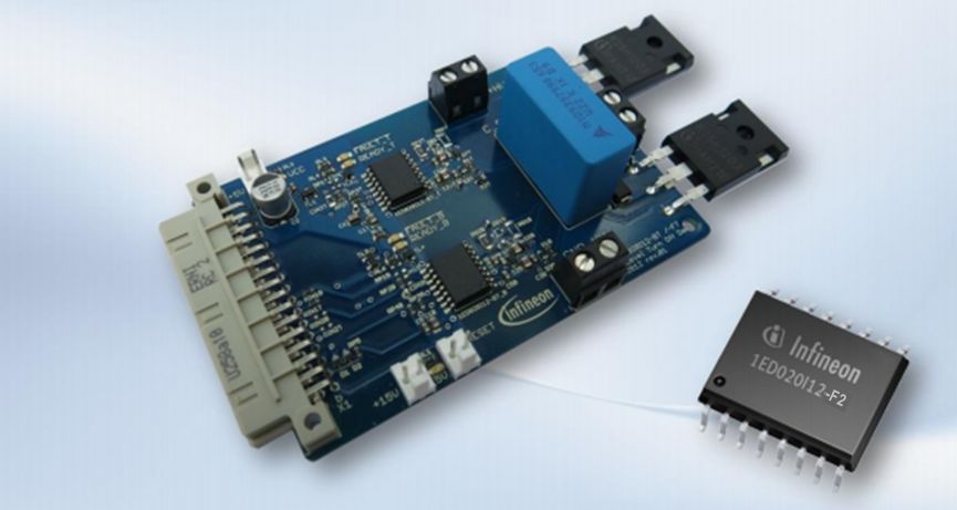
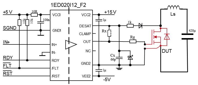
Figure 5 Short circuit test platform based on IMW120R045M1 (TO-247-3pin) and 1ED020I12-F2
b) Test waveform and results
There are 4 signals in the test waveform, CH1 is the voltage signal measured at the 1ED020I12-F2 desat pin, and CH2 is the drain current measured by the Rogowski coil PEM CWT-3B. CH3 and CH4 are drain-source voltage (Vds) and gate-source voltage (Vgs) respectively
The test waveform is shown in Figure 6. The initial peak value of the short-circuit current reaches 250A. The voltage of 1ED020I12-F2's DESAT pin rises linearly after the start of the short circuit and reaches 9V at about 2us. Then the drive chip starts to turn off the output and pulls down the drive voltage to a negative value. The SiC MOSFET is successfully turned off within 2.5us. .
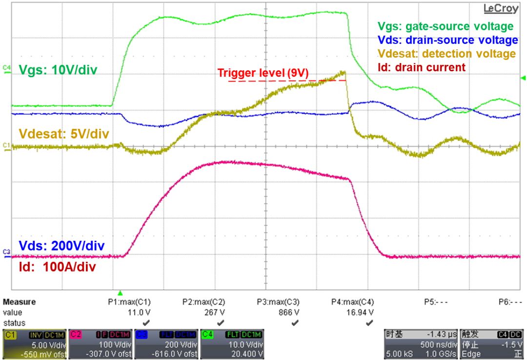
Figure 6 Short-circuit test waveform based on IMW120R045M1 (TO-247-3pin) and 1ED020I12-F2
in conclusion
In practical applications, the gate voltage is very important for driving SiC MOSFETs. Although a higher driving voltage can bring the benefit of reducing RDSON, a higher gate voltage will bring a higher short-circuit current. Through testing, we can see that for IMZ120R045M1, under the condition of bus voltage 800V, gate voltage 18V, and short circuit pulse 4us, the device will fail in short circuit. Therefore, we still recommend a positive driving voltage of 15V in consideration of the trade-off between conduction characteristics, gate oxide lifetime and short-circuit protection.
Compared with IGBT, SiC MOSFET has a shorter short-circuit withstand time. However, by selecting the appropriate driver IC and peripheral circuit settings, the SiC MOSFET can still be turned off safely in the event of a short circuit, thus building a very robust and reliable system.
Blue light filter-using blue light filter technology can eliminate blue light on the phone screen, thereby reducing eye fatigue and fatigue. And keep your eyes healthy and avoid staring at the screen.
Ultra-transparent and protective Ultra-high-quality Ultra HD provides you with clear viewing effects. Let you fully enjoy the super retina display of the screen.
Evacuation Waterproof and Waterproof-The hydrophobic and loose oil transparent layer is used as the final coating to protect screen fingerprints, liquid residues and other stains, keeping your phone in its original condition all day long.
The 0.14mm high-sensitivity touch Ultra-Thin Protective Film can provide real touch and high sensitivity, ensuring that the original high-response touch is not disturbed.
If you want to know more about Anti-Blue Light Screen Protector products, please click the product details to view the parameters, models, pictures, prices and other information about Anti-Blue Light Screen Protector.
Whether you are a group or an individual, we will try our best to provide you with accurate and comprehensive information about the Anti-Blue Light Screen Protector!
Anti-blue Screen Protector, Anti-blue Light Protective Film, Anti-blue Light Screen Protector,Anti Blue Light Screen Protector,Blue Light Blocking Screen Protector
Shenzhen Jianjiantong Technology Co., Ltd. , https://www.jjtscreenprotector.com