The eight-way digital display responder mainly has the advantages of simple circuit, low cost, convenient operation, sensitive and reliable, and has good operability through good use effect. The eight-way answering device consists of eight sets of switches and one LED display. Which group first presses the group's answering switch, and the LED light in front of which group will light up. In the future, pressing any of the answering buttons will not reflect. The next answer can only be made after pressing the reset again.
hardware design(1) Design a digital responder that can accommodate eight groups (or more) of entries, each set with a button for answering.
(2) The responder has a first signal discrimination and latching function, so that buttons other than the first responder do not function.
(3) After the certain time is over, the digital tube is cleared, waiting for the next call to start.
The design block diagram is shown below.
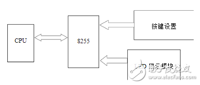
The 8255 adopts the 90H operation mode, that is, the PA port is the input, and the PB and PC are the outputs. Connect the eight responder buttons to PA0~PA7 of the 8255 chip. When the 8 buttons are not pressed, the 8-bit rush state sent to the parallel interface is 0. When the button change is detected, the microcomputer is detected. When the sampled data of the 8 bits is not 0, the microcomputer samples the 8 channels of the answer signal through the parallel input port.
After analysis, the key of the experiment is to accurately judge the information of the responder. To this end, 8 responder buttons are connected to PA0~PA7, and the microcomputer samples the 8-way answer signal through the parallel input port. When the rush signal of which group has been sent, the group number of the group is recorded. The LED digital pipe segment code corresponding to the group number is output from the PB port, and the answer button number is displayed on the LED display.
When the 8th group has not pressed the answer button, the 8-bit rush state sent to the parallel interface is empty, and when the microcomputer samples the 8-bit data is not 0, it means that a group has obtained the chance to get a reply, and then pass By querying the status of the bit by bit, you can determine which group is successful in the answer, and finally use the parallel output interface to make the group number that successfully grabs. In the experiment, only one 7-segment digital tube can be used to display the group number of the answering player.
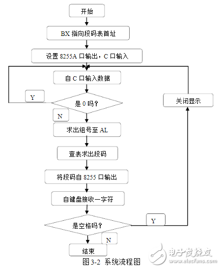
The system design flow chart is as follows
Data segment
Ioport equ 0d400h-0280h
Io8255a equ ioport+28ah
Io8255b equ ioport+28bh
Io8255c equ ioport+288h
Led db 3fh, 06h, 5bh, 4fh, 66h, 6dh, 7dh, 07h; digital watch
Data ends
Code segment
Assume cs:code,ds:data
Start:mov ax,data
Mov ds,ax
Mov dx, io8255b; set 8255 for A port output, C port input
Mov ax,89h out dx,al
Mov bx, offset led ; make BX point to the first part of the code tube
Sss: mov dx, io8255a
In al,dx ; input data from port 8 of 8255
Or al,al ; compare is 0
Je sss ; if 0, it means no key press, turn sss
Mov cl,0ffh ;cl as the counter, the initial value is -1
Rr: shr al,1
Inc cl
Jnc rr
Mov al,cl
Xlat
Mov dx, io8255c
Out dx,al
Mov dl,7 ; bell ASCII code is 07
Mov ah, 2
Int 21h
Wai: mov ah,1
Int 21h
Cmp al, 20h; whether it is a space
Jne eee; no, turn eee
Mov al,0 ;Yes, turn off the light
Mov dx, io8255c
Out dx,al
Jmp sss
Eee: mov ah, 4ch; return
Int 21h
Code ends
End start
CIXI MEMBRANE SWITCH FACTORY , https://www.cnjunma.com