Based on cavity mode theory, combined with multi-feed point network and short-circuit pin loading technology, a dual-band circularly polarized laminated microstrip antenna is proposed and designed. The simulation by time domain finite difference method (FDTD) shows that the structure can realize dual-frequency circular polarization and has the characteristics of small size and frequency bandwidth. These characteristics make it an important development in the future wireless communication field. And application prospects.
The Global Navigation Satellite System (GNSS) provides precision for a wide range of users due to its versatile (terrestrial, marine, aerospace and aerospace), global, all-weather, continuous and real-time navigation, positioning and timing functions. Three-dimensional coordinates, three-dimensional speed and time information are favored by people. The antenna plays a decisive role as the terminal of the satellite navigation system, and its performance directly affects the entire system.
Terminal antennas commonly used in global satellite navigation systems are available in four-arm helical antennas and microstrip antennas. The four-arm helical antenna can form different radiation patterns by changing its physical size to meet the application requirements of different spaces, but its disadvantages greatly limit its development due to its high cost and large axial size. At the same time, the emergence of microstrip antennas has made people see hope. Because of its small size, low profile, conformity with the carrier, and easy realization of circular polarization, it has received great attention, and the frequency band is narrow, the gain is small, etc. Disadvantages also hinder its development, but at the same time attract a lot of research. At present, microstrip antennas based on different number of feed points and new patch structures have been extensively studied. Chari Ricky and Mak Chi-Lun et al. proposed to obtain a satisfactory bandwidth by opening an E-groove on the patch, but the antenna size of this method is large. In the literature, a circular microstrip antenna and a rectangular microstrip antenna loaded with shorting pins are introduced, and the antenna size is reduced by 89% at the operating frequency of the antenna. In this paper, a novel laminated microstrip antenna is proposed and designed by combining the above two methods. By rotating four slots symmetrically on the patch and using a rotary feed that makes the phases between the feed points 90° out of phase. The technology effectively extends the impedance bandwidth of the antenna and reduces the size of the antenna by 26%.
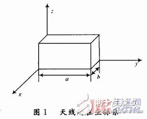
1 theoretical analysis of the laminar membraneSelect the coordinate system shown in Figure 1. When h ""0, assume that the magnetic field between the patch and the ground plate is only Hx and Hy components, the electric field has only the Ez component, the inner field does not change with the z coordinate, and the surrounding is the magnetic wall. There is an electric wall between the piece and the ground plate.
Ez satisfies the wave equation:


Hx and Hy can be solved by Maxwell's equations:

That is, the field distribution in the cavity is obtained, and the resonant frequency of the antenna can be obtained as follows:
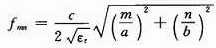
From the above calculations, the patch sizes a and b of the antenna are obtained, where a and b are equivalent dimensions considering the edge effect, and the relationship between it and the physical dimensions a' and b' is:

They are the thickness of the substrate and the equivalent dielectric constant.
2 Antenna model design and optimizationBased on the cavity membrane theory combined with surface slotting method (curved flow technology) and short-circuit pin loading technology, a novel micro-band antenna with miniaturized laminated structure is designed and optimized. The structure is shown in Figure 2. It consists of two layers of upper and lower patches, short-circuit probe and coaxial line. It adopts two-layer patch. The upper and lower layers are made of PTFE with the same dielectric constant (relative dielectric constant εr1= εr2= 4.4, the loss tangent is tan δ = 0.001), and the substrate thickness is 4 mm. The coaxial line is connected to the upper layer through the drilled hole of the lower layer patch, and the lower layer patch is a parasitic unit of the upper layer patch, which is directly fed by the probe. Two resonant frequencies of L1 (1.575 GHz) and L2 (1.227 GHz) are achieved by adjusting the size of the upper and lower patches. Based on the lobe width, efficiency and bandwidth performance considerations, a square microstrip patch is used as the radiating element, and four rectangular slots are symmetrically opened at the edge of the patch, which not only ensures the symmetry of the unit structure, but also achieves good symmetry. Orthogonal polarization radiation characteristics; by adjusting the size of the opened rectangular slot, the axial ratio bandwidth of the antenna is greatly improved under the condition that the reflection loss is substantially unchanged, so that the axial specific bandwidth is expanded to a certain extent; At the same time, since the surface current path of the patch is increased by slotting on the patch, the resonant frequency is reduced, thereby reducing the size of the patch, so that it meets the requirements required in practical applications.
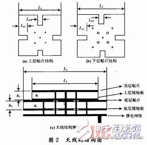
The electromagnetic simulation software CST was used to simulate the designed antenna by the finite difference time domain method. Through simulation analysis and optimization, the lower patch size L2 & TImes; L2=51.6 mm & TImes; 51.6 mm, the size of the gap Ls2 & TImes; Lw2 = 10.2 mm & TImes; 5 mm, upper patch size L1 × L1 = 39.5 mm × 39.5 mm, slit size Ls1 × Lw1 = 7.8 mm × 5 mm. The antenna-based symmetrical structure uses eight coaxial feed points to feed the antenna. The upper and lower two-layer patches use four feed-point misalignment feed technologies to keep the phase center and circular polarization performance of the antenna stable.
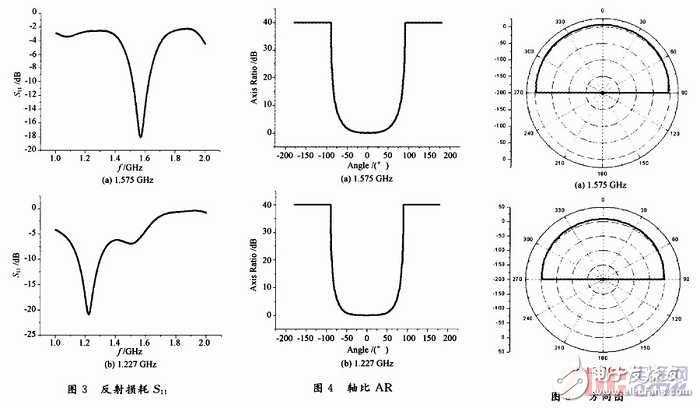
The simulation results obtained according to the previous design are shown in Figs. 3 to 5 . The antenna has a reflection loss of S11 "-10dB" in the 1.521~1.629 GHz and 1.153~1.313 GHz bands, and the reflection loss S11 at the center operating frequency of 1.575 GHz and 1.227 GHz, respectively. -18.1 dB and -20.9 dB (as shown in Figure 3). Figure 4 shows the simulation results of the polarization axis ratio of the antennas in the 1.575 GHz and 1.227 GHz bands. It can be seen that at 1.575 GHz, the antenna has a polarization axis ratio of less than 3 in the range of -59° to 59°. dB; at 1.227 GHz, the antenna has a polarization axis ratio of less than 3 dB from -65° to +65°. Figure 5 shows the simulation results of the circularly polarized antennas in the 1.575 GHz and 1.227 GHz bands. The simulation results show that when the frequency is 1.575 GHz, the gain of the antenna in the ψ=0° direction is 6.1 dB, half power width is 104.5°; when the frequency is 1.227 GHz, the antenna gains 8.4 dB in the ψ=O° direction and the half power width is 90.9°. Meet the requirements of the actual project.
The two-layer structure microstrip stacking structure was analyzed and designed by the application of cavity film theory and time domain finite difference method. The design of the laminated microstrip antenna combines the meandering technique and the load shorting pin technology, and is simulated using CST electromagnetic simulation software. The simulation results show that the gain and impedance bandwidth of the antenna are better than the rectangular patch microstrip antenna of the same structure, which fully meets the performance requirements of the GNSS antenna. The antenna also has many advantages such as simple structure, small size and easy processing. Important applications are available in the field of wireless communications.
Screen Protector,Uv Glue Screen Protector,Uv Tpu Film Screen Protector,Uv Curing Screen Protector
Shenzhen TUOLI Electronic Technology Co., Ltd. , https://www.hydrogelprotectors.com