Feasibility analysis of a project
background analysis:
The autonomous flight technology of unmanned aerial vehicles has been a hotspot in the field of aviation for many years, and there are a large number of needs in practical applications. The main advantages include: low system manufacturing cost, low personal injury when performing tasks, excellent controllability and flexibility. Sex and so on. The advantages of the rotary wing aircraft compared with the fixed-wing aircraft include: less space required for take-off and landing of the aircraft, strong controllability in an obstacle-dense environment, and high attitude maintaining capability of the aircraft. Compared with other aircraft, the small quadrotor has the advantage of simple mechanical structure and control by changing the speed of the four motors, and the flight maneuverability is more flexible. On the other hand, the small quadrotor has high maneuverability and the ability to take off, hover, fly and land in a small area.
Therefore, based on the characteristics of the four-rotor aircraft, we propose a general structure of a digital flight control system. The flight control computer is a basic component of the quadrotor autopilot. Using a modular design concept, a flight control computer based on the PIC32 high-performance microcontroller is designed and developed. The quadrotor uses a symmetrically distributed structural form to establish a nonlinear mathematical model. By introducing four control quantities, the nonlinear model is decomposed and linearized, and the simplified linear model of the quadrotor in hovering state is obtained. The classical PID control method is used, and the digital simulation results are analyzed to verify the feasibility of the control scheme. At the same time, the structural shape of the quadrotor and the main hardware with sensors, flight control computer and actuator as the core should be implemented in hardware and software.
Second project content
This project studies four-axis aircraft to realize functions such as flight, sampling and data transmission. There are many technologies involved, including software algorithms, microelectronics, analog electronics, mechatronics, and automatic control theory. Therefore, the project team will analyze this part and overcome it one by one.
Theoretical analysis of flight control systems, establishment of mathematical models, hardware selection and principle design
Before studying the four-rotor aircraft control algorithm, the dynamic model of the aircraft system must first be established. In this chapter, we first introduce the basic methods of modeling: select the key forces and moments that affect the motion of the aircraft, and then establish the dynamic equations of the aircraft according to the corresponding laws of physics. Then, after obtaining the dynamic equation of the quadrotor, the control quantity is appropriately selected, and the classical PID control algorithm in the control theory is applied. Control the aircraft system.
2. Software programming, hardware construction at the same time
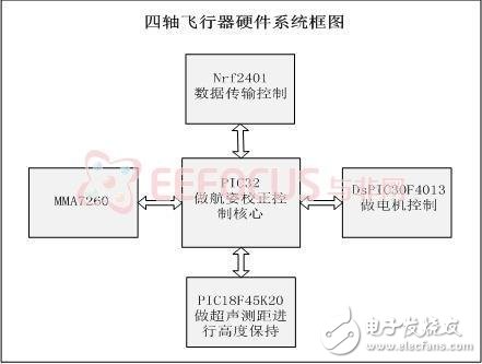
Taking into account the conditions of the real laboratory, the following hardware aspects are used to adopt the PIC32 for the attitude correction control core, the DsPIC30F4013 for motor control, the PIC18F45K20 for ultrasonic ranging for high-level maintenance, the nRF2401 for data transmission, and the acceleration sensor MMA7260. Figure 1 is a block diagram of the system.
The attitude control algorithm is implemented:
The attitude control algorithm should include attitude control and navigation behavior control. The air attitude control should be autonomously completed, including the spin, pitch, roll and altitude of the aircraft.
The navigation behavior control is mainly operated by the operator to remotely operate the aircraft through wireless transmission. If the air attitude is well controlled and maintained, then the problem of navigational behavior control will be solved. So the following focuses on air attitude control issues. For the convenience of description, it is briefly illustrated by the following figure, and the subsequent descriptions are all referenced to the figure:
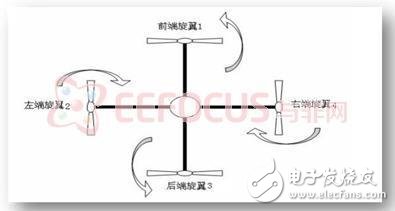
All control behavior of the quadcopter is achieved by adjusting the speed of the four power motors.
First, in order to overcome the spin of the aircraft, any two adjacent motors must be turned to the opposite direction; while the opposite pair of motors are turned in the same direction (as shown in the figure above), the torque of the two pairs of motors is precisely adjusted to offset the counter torque. In order to avoid a change in the angle of the aircraft's roll or pitch during this adjustment, it is necessary to synchronously change the rotational speed of a pair of motors that are opposite in position.
Secondly, in order to keep the aircraft level, it is necessary to change the speed of a certain motor to maintain the level again. This adjustment will cause the imbalance of the four motors' reverse torque, causing the aircraft to spin, so it is necessary to adjust the relative position of the relative position synchronously. The speed of the rotating motor is brought back to equilibrium. For example, if the aircraft is tilted to the right due to some disturbance, it is necessary to increase the rotational speed of the motor to increase its lift. This behavior will cause the whole aircraft to increase the clockwise torque and start to spin, so while increasing the rotational speed of the motor. It is necessary to reduce the rotation speed of the motor B synchronously to offset the increase of the counter torque.
Finally, in order to maintain a high degree of stability, the real-time altitude of the aircraft needs to be detected by some means. The currently considered solution is ultrasonic ranging, and the possibility of laser ranging and GPS is not excluded in the future. However, ultrasonic ranging and GPS division of labor are different. Ultrasonic ranging is mainly responsible for height detection in the range of 0 to 10 m, and the accuracy of GPS determines that it is only suitable for maintaining height in the case of high altitude.
All of the above mentioned are the principles of control, and the specific means need to be realized by the single-chip microcomputer. If you want to achieve better control results, the PID algorithm is essential. At the same time, the three adjustment processes need to be organically combined to form a complete attitude control algorithm system. The three interact with each other and refer to each other to achieve the goal. For example, if you keep the level, you need to check the spin at any time and adjust it in time.
3. Test the program to complete the initial function of the aircraft
4. Further modifications to reduce aircraft power consumption and improve aircraft performance
The open frame industrial monitor that we offer are a range of monitors without front bezel--all kits: TFT LCD panel (touchscreen), LCD controller board, inverter and cables mounting into a back enclosure. It is low profile design, suit for self-mounting into kiosks, cabinets, consoles, machines and control panels. This monitor is ideal for integrators and OEMs for special mounting applications.
open frame monitor,open frame lcd monitors,open frame touch screen,open frame touch monitor,open frame displays,open frame lcd display
Shenzhen Hengstar Technology Co., Ltd. , https://www.angeltondal.com