A DC regulated power supply provides an electronic device that provides a stable DC power supply to the load. The power supply of the DC stabilized power supply is mostly AC power. When the voltage or load resistance of the AC power supply changes, the DC output voltage of the regulator will remain stable.
The DC stabilized power supply is a device that converts 220V power frequency AC power into a regulated DC voltage. It needs to be transformed, rectified, filtered, and stabilized. The four links work as follows:
(1) Power transformer: It is a step-down transformer that converts the 220V AC voltage of the power grid into an AC voltage that meets the needs and sends it to the rectifier circuit. The transformer ratio is determined by the secondary voltage of the transformer.
(2) Rectification filter circuit: The rectifier circuit converts the AC voltage Ui into a pulsating DC voltage. The filter circuit filters out the large ripple component and outputs a DC voltage U1 with a small ripple. Commonly used rectification and filtering circuits include full-wave rectification filtering and bridge rectification filtering.
(3) Filter circuit: Most of the AC components in the output voltage of the rectifier circuit can be filtered out to obtain a relatively smooth DC voltage. Each filter capacitor C satisfies RL-C=(3~5)T/2, or T For the input AC signal period, RL is the equivalent load resistance of the rectification filter circuit.
(4) Voltage regulator circuit: The function of the voltage regulator circuit is to stabilize the output DC voltage and not change with the AC grid voltage and load changes. Commonly used integrated regulators are fixed three-terminal regulators and adjustable three-terminal regulators. Commonly used adjustable positive voltage integrated regulators are available in the CW317 (LM317) series. Their output voltages are adjustable from 1.25V to 37V. The simplest circuit external components require only one fixed resistor and one potentiometer. The chip has transition, overheat and safe working area protection, and the maximum output current is 1.5A. The typical circuit is as shown in the following figure. The resistor R1 and the potentiometer R2 form an output voltage regulator. The expression of the output voltage Uo is: Uo=1.25 (1+R2/R1) where R1 is generally 120-240 ohms, and the output terminal and the adjustment terminal are The dropout voltage is the regulator's reference voltage (typically 1.25V).
In the circuit, D5, D6 and C1 form a full-wave rectification and filtering circuit, which converts the input AC power into DC power; Q1 and Q2 form a Darlington injection circuit, Q1 is called an adjustment tube, and Q2 is called a push tube. Power supply; Q3, D8, R2, R3, RW1 together constitute the output voltage sampling negative feedback circuit, Q3 is called the sampling amplifier tube, D8 is called the reference voltage regulator tube, this part is used to stabilize the output voltage; Q4, R5 constitute the output current sampling The circuit provides overcurrent protection for the output; C5 is the output filter capacitor. Since the regulating tube and the load are connected in series with respect to the input, this power source is called a series-type DC regulated power supply.
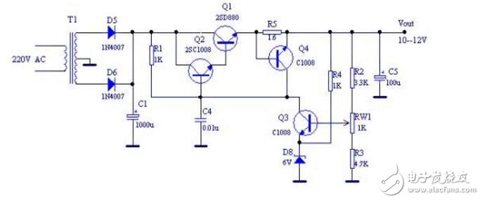
Figure 1 DC stabilized power supply schematic
After the 220V AC power is stepped down to low-voltage AC power, the full-wave rectification and filtering circuit composed of D5, D6, and C1 is rectified and filtered to become DC power, which is sent to the Darlington injection circuit, and finally the DC voltage is supplied to the load by the injection-assisted circuit. VO, the magnitude of this voltage VO is determined by the reference voltage VREF and the voltage division ratio of the sampling branch. When the output voltage VO rises instantaneously for some reason, the collector current of Q3 of the output voltage sampling circuit increases, causing the base current of the emitter to fall, the internal resistance of the adjustment tube increases, and the tube pressure drop increases. The output voltage VO is lowered; when the output voltage VO is instantaneously decreased, the collector current of the output voltage sampling circuit Q3 is decreased, the base current of the injection circuit is increased, and the tube voltage drop is reduced, thereby making the output voltage VO also rises; the above process stabilizes the output voltage at a certain voltage value, thereby achieving regulation. The output voltage value can be changed by adjusting RW1.
When the load current exceeds the rated output current, the voltage drop across R5 will turn Q4 on, forcing the bias voltage of the shoot-in circuit to decrease, the internal resistance to increase, and the tube voltage drop to increase, the output current of the shooter is limited. The output voltage is also reduced, thereby providing overcurrent protection. This structure belongs to the current limiting protection circuit.
The input 220V AC voltage is stepped down by the transformer, and the output is pulsating DC voltage after rectification by the rectifier diode. It has a large voltage ripple. After the smooth filtering of the capacitors C1, C2 and C3, the output voltage is relatively stable, and then input to the voltage regulator. The circuit can get a stable DC voltage regulated power supply with small voltage ripple at the output.
The use of DC stabilized power supplyDC stabilized power supply is widely used in DC power supply for national defense, scientific research, universities, laboratories, industrial and mining enterprises, electrolysis, electroplating, charging equipment, etc.
(1) It can be used for aging of various electronic devices, such as aging of PCB board, aging of household appliances, aging of various IT products, aging of CCFL, aging of lamps
(2) Applicable to the aging and testing of electronic components that require automatic timing, power-off, and automatic cycle counting.
(3) Electrolytic capacitor pulse sophisticated
(4) Responsive testing of resistors, relays, motors, etc.
(5) sophisticated machine; electronic component performance test, routine test.
Type2 Tethered Cable,Tethered Cable,Tethered Type 2 Cable,Type 2 Tethered Charging Cable
Yangzhou JERI New Energy Co., Ltd. , https://www.jrevcharging.com