 The following is the circuit diagram of [X9313 digital control potentiometer internal structure circuit]
 The X9313 is an industrial-grade 32-tap digitally controlled potentiometer with a maximum resistance of 10 kΩ and is available in 8-pin packages in DIP, OIC, and FSSOP packages. The internal functional block diagram of the X9313 is shown in the figure. It consists of an input part, a 5-bit E2PROM, a memory and recall circuit, a 32-select decoder, a 32-channel analog switch consisting of a MOS field effect transistor, and a resistor array. The input part is a 5-bit up/down counter via a three-wire add/drop interface ( 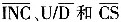 Connected to the microcontroller, it works like a up/down counter, the output is decoded, and the control turns on an electronic switch, thus connecting a point on the resistor array to the sliding output. The resistor array consists of 32 equivalent resistors and associated electronic switches. Depending on the level of the console, the contents of the counter can also be stored in non-volatile memory for subsequent use.
The two top leads are connected to VH and VL, respectively, and the middle tap is VW. For 3 consoles, among them,  For the chip selection, When low, the X9313 is selected. Can receive at this time
  signal of.
  The counter is incremented or decremented by one on the falling edge. in case,
  The sliding end slides in the VH direction, and the resistance between VW and VH is reduced by one step. On the contrary, if,
  The sliding end slides in the VL direction. After the counter output is decoded, after 32 is selected, the position of the wiper is moved along the resistor array. When the counter reaches an extreme (00000 or 11111), it will not loop back, from 00000 to 1111l, or from 11111 to 00000, that is, when the counter Is high Also when high, the value of the counter is stored in non-volatile memory. When the system is powered up, the device automatically sends the value in the non-volatile memory to the counter as the output of the counter.
|
S/N
|
Project
|
General Parameter
|
|
1
|
Number of series
|
15S
|
|
2
|
Rated voltage
|
48V
|
|
3
|
End of discharge voltage
|
40V
|
|
4
|
Charging voltage
|
Recommend 51V (50.5V – 51.5V) for floating charge
Recommend 54V (53.5V – 54.5V) for equation charge |
|
5
|
Continuous charge and discharge curren
|
≤100A
|
|
6
|
Internal resistance (battery pack)
|
≤100mΩ
|
|
7
|
Self-discharge rate
|
≤2%/month
|
|
8
|
range of working temperature
(≤95%R.H.) |
0~65℃ charge
-20~65℃ discharge |
|
9
|
Storage temperature range(≤95%R.H.)
|
-40~70℃
|
|
10
|
Positive and negative lead way
|
Fence Terminal 2P*2
|
|
11
|
Display screen
|
LED display, four physical buttons
|
|
12
|
Protective function
|
Overcharge, over discharge, short circuit, overload, over temperature, etc.
|
|
13
|
certificate
|
MSDS,ISO9001,CE,UN38.3,ROSH
|
LIFEPO4 Battery For Home Energy Storage
Jiangsu Zhitai New Energy Technology Co.,Ltd , https://www.zhitainewenergy.com