Abstract: Based on image enhancement method, this paper proposes an image debugging fast algorithm using luminance mapping. This algorithm improves the recognition of objects in the fog by adjusting the contrast of the outdoor foggy scene image. The algorithm has low complexity, small processing delay and high real-time performance, which is beneficial to the implementation of FPGA. The implementation does not require external memory, the delay is ns level, and provides an intensity adjustment interface to adapt to a wider application environment.
0 Introduction There are many research results on the processing technology of fog image. However, most defogging algorithms are based on multiple images or other information to defogg, which greatly limits the scope of the algorithm. The defogging algorithm based on single image, such as the widely used dark channel method, is mostly applied to the PC environment, the processing method is complex, the processing speed is slow, and it is necessary to traverse the image multiple times. Taking the dark channel method as an example, it takes 10 to 20 seconds to process the 600&TImes; 400 resolution fog image using the 3.0GHz Pentium 4 processor, which is difficult to perform real-time processing in the embedded environment.
However, the above-mentioned defogging algorithm is designed to completely remove the fog effect in the image to improve the visual perception of the naked eye. In real-time applications such as military and surveillance, it is often unnecessary to remove the fog to improve the look and feel, but only to increase the interest. The degree of identification of the area to find objects hidden in the fog. Therefore, how to improve the object recognition degree in the original image with the fog-affected area is a key point for real-time dehazing processing in these application scenarios.
The processing goal of the fast algorithm used in this paper is to use the brightness distribution characteristics of the fog image to improve the recognition of the distant object affected by the fog in the original image by using the image enhancement method. The algorithm complexity is low, and the optimized FPGA implementation can achieve ns-level delay.
The outdoor foggy environment changes the atmospheric scattering conditions due to the fog in the air, causing contrast degradation of the captured object image. The mathematical model of the widely used fog image is shown in equation (1).
I(x)=J(x)t(x)+A[1-t(x)] (1)
In the formula (1): I is the observed foggy image, J is the scene image without fog, A is atmospheric light, and t is transmittance. Therefore, to complete the defogging is to calculate J, t, A by I and some prior conditions.
The algorithm of this paper mainly focuses on the influence of atmospheric illumination parameter A on the image. Let t=0, I=A can be obtained. Visible A refers to the atmospheric illumination image observed when there is no object in the scene. Since the visual information of the object is reflected by the object under atmospheric illumination, the object absorbs part of the light during the reflection, resulting in loss of brightness. Therefore, A is usually the highest brightness of the entire fog image, so the following diagram is used to further illustrate the principle of degradation.
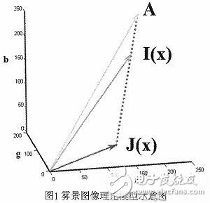
It can be seen from the formula (1) in combination with FIG. 1 that the fog image can actually be regarded as a result obtained by superimposing a layer of a bright white image on the original fog-free image in proportion, and the superposition ratio parameter is determined by the transmittance. t, the higher the transmittance, the smaller the effect of fog on imaging and the closer the resulting image is to reality. In an outdoor scene, when the fog concentration distribution is uniform, the farther the object is from the camera, the lower the transmittance, that is, the higher the degree of degradation of the collected object image. Since A is usually the highest brightness of the entire image, the brightness of the object in the fog will also increase as the degree of degradation increases.
Therefore, from the theoretical model we can get the following conclusion: In the usual fog image, the farther the object is from the camera, the higher the degree of degradation of the image, and the higher the brightness. That is, the brightness and degree of degradation of the fog image have a certain degree of positive correlation.
Based on the above analysis, we can enhance the recognition of objects with more degraded areas in the fog image by enhancing the contrast of the image in the high-brightness area. We use equation (2) to map the luminance to achieve contrast enhancement for high luminance regions. The brightness mapping curve corresponding to the formula (2) is as shown in Fig. 2, and the contrast curve should have the brightness mapping curve obtained by the contrast adjustment using the function shown in the formula (2).
In the formula (2), the parameter p is the enhancement intensity, and the value range is [0, 1). When p=0, Yout=Yin is not enhanced.
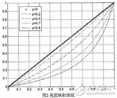
The flat line at p=0 in Fig. 2 is a standard contrast curve. It can be seen that the slope of the curve of the algorithm is small when the brightness is low, and the slope gradually becomes larger as the brightness becomes higher. And the slope changes continuously and the curve is smooth to reduce image distortion caused by contrast adjustment. At the same time, as p increases, the curvature of the curve becomes severe.
2 FPGA implementationFor FPGA-based hardware processing, the floating point number of the original [0, 1) needs to be corresponding to the fixed-point integer domain of [0, 255] for processing. Therefore, this algorithm only needs to establish and maintain an 8-bit 256 brightness mapping table for the FPGA, which is suitable for implementation in FPGA.
2.1 Hardware Structure The hardware platform block diagram built by FPGA is shown in Figure 3. The analog standard definition PAL video is converted into digital video input into the FPGA through the AD chip, and the video is defogged in the FPGA, and the processed digital video is output to the DA chip and then converted into a PAL output for display display.
The digitized PAL signal conforms to the BT.656 standard and is a YUV digital video with a sync code embedded therein, wherein the Y component is a luminance component, and the FPGA performs defogging processing on the component.
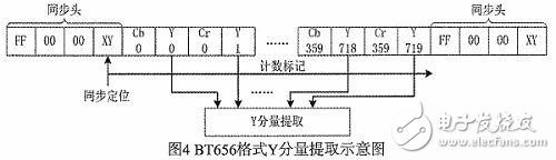
The BT656 video format and the Y component extraction method are shown in FIG.
According to the embedded synchronization head in the BT.656 code stream, the data is located, and then the stream data after the positioning is counted, and the even number of data shown in FIG. 4 is the Y component, which is extracted and used by the algorithm. deal with.
2.2 Algorithm Optimization Since the image acquired in the real scene often cannot be saturated with brightness, if you use equation (2) directly, a large number of pixels are mapped to the low-luminance part curve, which in turn lowers the overall contrast and does not get too good results. Therefore, the original formula needs to add the maximum brightness Ymax parameter, (Ymax, 255) as the convergence point of the curve, and the calculation of equation (2) is processed into the fixed-point integer domain calculation to facilitate the hardware implementation, and finally the optimized formula is obtained:
The effective digits of Yin, P, Ymax, and Yout in equation (3) are all 8 bits, and the value range is [0, 255), that is, the normalized value of the variable becomes 255. Where Ymax is the maximum brightness in a frame of image pixels. When Ymax=210, the luminance curve obtained by equation (3) is as shown in FIG. 5.
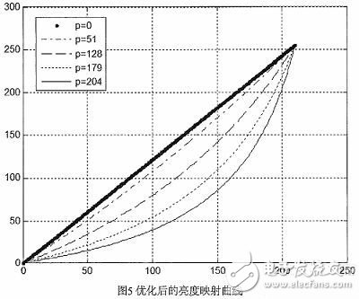
As can be seen from FIG. 5, the optimized luminance mapping curve is basically the same as that of FIG. 2, but the convergence point becomes (Ymax, 255), thereby improving the effectiveness of the luminance conversion.
Since the maximum brightness in the image is to be counted, it is necessary to traverse the image once, which increases the delay of 40 ms (transmission time of one frame of PAL image). In the actual processing, the difference between the video frames can be utilized, and the Ymax of the previous frame is taken as the parameter of the current frame processing. Since Ymax is the maximum value of the previous frame, the algorithm may process that the Yin of the current frame is larger than Ymax, so that the Yout value obtained by the mapping may overflow (greater than 255). Therefore, when establishing and updating the mapping table, the value of the calculation result greater than 255 needs to be clamped to be equal to 255, and the block diagram of the FPGA logic obtained by the above method is as shown in FIG. 6.
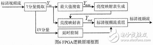
The Y component extraction module in FIG. 6 extracts the Y component in the input video stream and branches it to two-way processing, and performs a maximum value search for one time. When one frame ends, Ymax is output to the luminance mapping table generating module to generate a new frame brightness. The mapping table; the other branch of the branch queries the current luminance mapping table, and obtains the enhanced Yout, and finally combines the UV component into the standard definition video stream and outputs it to the AD chip for PAL encoding.
2.3 Defogging effect and performance The processing effect for several fog scene images is shown in Figure 7.
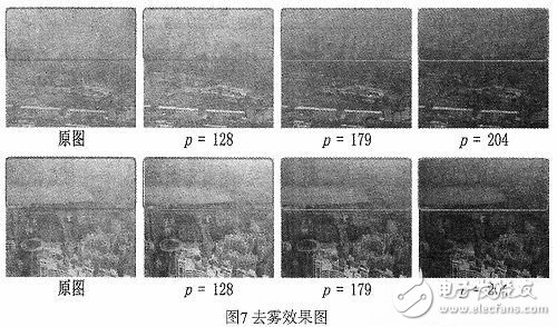
The effect of the treatment can be seen from Fig. 7. The contrast of the upper part of the foggy image is enhanced after the enhancement processing, and the objects in the original image area are blurred, and the texture features are basically recognizable as the enhancement intensity is improved.
However, this improvement effect is at the expense of reducing the overall brightness of the image. As the parameter increases, the overall brightness gradually decreases. Therefore, under different lighting conditions, different P values ​​can be obtained to obtain better sensory effects.
In terms of processing performance, since the Ymax of the previous frame image is used in the creation and update of the mapping table, when the current frame is processed, the table has been updated in the blanking time after the end of the previous frame image. Therefore, when the Yin input is directly checked, the enhanced Yout is obtained, and the delay is only one clock cycle. In the design completed in this paper, the 27 MHz clock is used as the system clock, that is, the delay is about 37 ns.
The algorithm uses Xilinx's low-end series Spartan3's XC3S400AN implementation, which only occupies 402Slices, 3 multipliers and 54Kbit block ram, can run up to 142MHz, and does not require any off-chip storage resources. The system realizes low cost and low power consumption. , high real-time.
3 SummaryAiming at the outdoor foggy environment, the brightness of the scene in the fog is high, but the contrast is low. This paper proposes an image enhancement algorithm using brightness mapping. Based on this algorithm, the brightness mapping table can be quickly established, and the contrast of the multi-fog area of ​​the image can be improved by using the look-up table method to improve the brightness of the input image, which can effectively improve the recognition degree of the object in the foggy scene. The logic circuit implemented in the FPGA has low complexity, strong real-time performance and less resource occupation.
Switch Junction Box,Electrical Wall Box,Waterproof Outlet Box,Electrical Adapter Box
FOSHAN SHUNDE LANGLI HARDWARE ELECTRICAL CO.LTD , https://www.langliplastic.com