Embedded CPU on the FPGA chip is the hardware CPU function realized by software programming, which is the development trend of embedded technology. Here, the sampling circuit, signal conditioning circuit, overweight alarm circuit and display circuit are designed for the weighing system, and at the same time, it is embedded for software. Technology, and the spartan6XC6SL development board as the core, wrote the software CPU and successfully embedded in the X45-CSG324 chip on Xilinx's spartan6XC6SL development board, realized the design of the smart car weighing and measuring instrument.
Digital intelligent load cells and digital weighing systems are hotspots in the field of electronic weighing and weighing in recent years. With the advancement of science and technology, the level of automation of industrialization processes, especially the development of digital technology and information technology, has put forward digital and intelligent requirements for electronic weighing systems. The traditional weighing system has a small output analog signal, generally 20~40mV; the transmission distance is short; the anti-interference ability is poor; the weighing control instrument is complicated; the congenital defects such as inconvenient installation and debugging can not adapt to the intelligence of the electronic weighing instrument. Requirements. In order to solve these problems, the single-chip system design is generally adopted. The above problems are basically solved, but the design circuit is quite mixed. This paper uses the powerful FPGA chip XC6SLX16-3CSG324 to make the peripheral circuit simpler, smaller, and more superior.
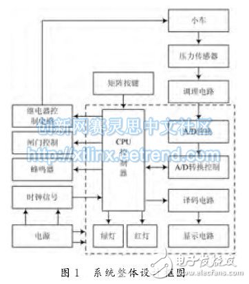
1 overall system designThe system is mainly composed of hardware circuit and FPGA program design. As shown in Figure 1, the hardware circuit design is based on the internal control part of FPGA chip X45-CSG324. The peripheral circuit has pressure sensor, conditioning circuit, relay control circuit, Buzzer drive circuit, display circuit, clock signal and buttons. The FPGA program module has A/D conversion and conversion control, CPU, decoding circuit, and the like. The system mainly controls the forward and reverse rotation of the trolley motor by controlling the relay switch. The forward and reverse rotations represent the forward and reverse of the trolley, so that the trolley can be parked in the proper position on the pressure sensor; the weight is converted by the pressure sensor. After the signal, input the FPGA chip through the conditioning circuit, internally realize 12 A/D conversion by programming, and send the A/D converted value to the CPU. After data processing, send it to the 12 display digital tube through the decoder to display the weight. The measurement range can be preset by the matrix button. If the green light is on, the gate is open, the trolley can pass; if the weight is less than the preset lower limit, the red light is on and the gate is not open; if it is greater than the preset The upper limit value, the red light is on and the buzzer alarms, and the gate does not open.
2.1 Sensor circuit design
2.2 conditioning circuit design
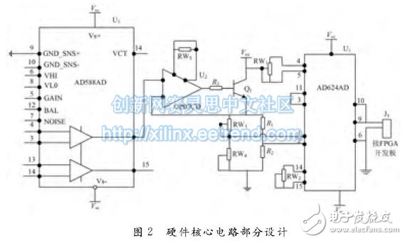
2.3 Other hardware circuits
The relay control circuit controls the front and rear movement of the trolley motor. The gate control circuit is actually the relay drive circuit, which controls the switch of the door. The buzzer circuit only needs a little triode drive. These three circuits are all used in the classic. The circuit is not described here.
3 software part design and implementation3.1 Software Design Flow Chart
The software design is divided according to the function module, real-time parallel control mode is adopted, and the FPGA program is carried out in the ISE13.3 integrated environment. The schematic circuit input mode, text input mode, module input mode and EDA design input tool can be used to express circuit construction ideas. . This system uses the commonly used Verilog HDL language text input to describe the function of the system. The software adopts a top-down design method, which is beneficial to the overall planning of the system's functions and performance, facilitating debugging and future maintenance. As the design level goes down, the parameters of the system are further refined and confirmed, and can be adjusted according to the design changes at any time, which is convenient for assigning the tasks of each functional module, thereby ensuring the correctness of the design and shortening the design cycle.
System software program flow chart shown in Figure 3.
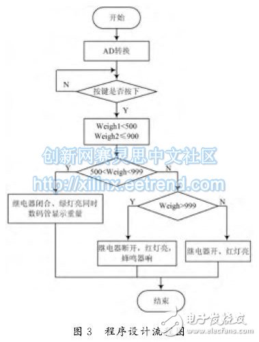
First, the signal received from the conditioning circuit is A/D converted. At this time, if the button is not pressed, it is in a waiting state. If pressed, the weight range boundary value is input and the weight range is determined. If it is within the range, the range is performed. The relay is closed to open the gate, the green light indicates that the car can pass, and the weight of the car is displayed at the same time; if it is outside the range, the second range determination is made to determine whether the overload is still insufficient or not. If the overload is overloaded, the relay remains disconnected, the red light The light and the buzzer sound double alarm. If the weight is insufficient, only the red light is on, the buzzer does not ring, and the gate does not open.
3.2 program simulation run
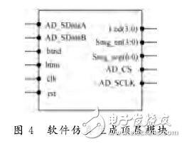
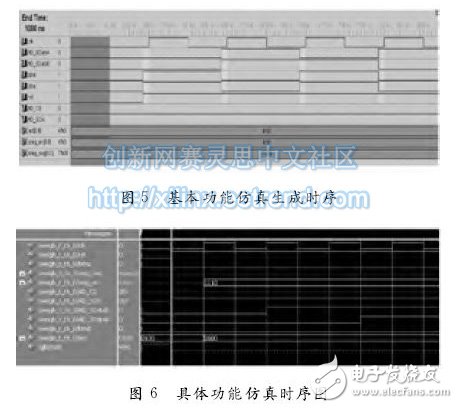
Connect the computer to the XC6SLX16-3CSG324 board. The board is connected to the car. After the system is powered on or reset, the initialization memory, register, control command data and port are initialized. After initialization, the card is initialized. Clock division setting, here mainly for chip clock and A/D clock setting, Figure 4 is the top-level module diagram generated by simulation, clk and AD_sclk are chip clock and A/D clock; btnd and btnu are the upper and lower limit setting parameters, this parameter Can be set and modified manually, other pins as shown in the figure, no longer explain; Figure 4 shows that the program design is correct, compiled through, and then mainly depends on whether the function can be achieved. Next, the simulation generates internal modules, each module corresponds to a program source code; then, the timing simulation is performed for each sub-module corresponding program, and FIG. 5 is a timing diagram of program initialization, which is a timing diagram when there is no input weight, from the figure It can be seen that the timing of A/D indicates 0. Here, it is mainly verified whether the digital tube is displayed as 0, whether the chip clock can work normally, whether the program can be downloaded to the board and successfully control the basic control part such as the car. After the completion of the basic part, the simulation of each part of the system is carried out. Only an important A/D simulation timing is input. As shown in Fig. 6, when the input weight is 0100, the whole circuit timing and A/D timing output are normal. The two warning lines at weights greater than 500g and below 1g are red and have no output. Consistent with the actual idea.
The author attempts to design an intelligent electronic scale using the FPGA method, designing in both soft and hard aspects, and carrying out simulation and practice. The scale is designed for the current situation of the use of single-chip development and design of intelligent electronic scales in China, and provides a reference for the development of intelligent electronic scales.
Vapesoul Disposable Vape Pen is so convenient, portable, and small volume, you just need to take them
out of your pocket and take a puff, feel the cloud of smoke, and the fragrance of fruit surrounding you. It's so great.
We are the distributor of the Vapesoul & Voom vape brand, we sell vapesoul disposable vape,vapesoul vape bar, voom vape disposable, and so on.
We are also China's leading manufacturer and supplier of Disposable Vapes puff bars, disposable vape kit, e-cigarette
vape pens, and e-cigarette kit, and we specialize in disposable vapes, e-cigarette vape pens, e-cigarette kits, etc.
vapesoul disposable vape pen device,vapesoul disposable vape pen kit,vapesoul disposable vape pen mod,vapesoul disposable vape pen mini,vapesoul disposable vape pen starter kit
Ningbo Autrends International Trade Co.,Ltd. , https://www.mosvape.com